Ink jet printing apparatus and ink jet printing method

a printing apparatus and ink jet technology, applied in the field of ink jet printing apparatus and ink jet printing method, can solve the problems of inability to make full use of the advantages of the block driving method, the inability to maintain the exclusive complementary relationship between the mask pattern a and b at a certain timing, etc., and achieve the effect of stably ejecting the ink

Inactive Publication Date: 2013-09-19
CANON KK
View PDF5 Cites 6 Cited by
  • Summary
  • Abstract
  • Description
  • Claims
  • Application Information

AI Technical Summary

Benefits of technology

[0011]The present invention provides an ink jet printing apparatus and an ink jet printing method which are based on the multi-pass printing method using a print head having a plurality of nozzle rows and which enables a reduction in the number of nozzles to be simultaneously driven, allowing ink to be stably ejected.
[0013]In the second aspect of the present invention, there is provided an ink jet printing apparatus printing an image on a print medium by allowing a print head capable of ejecting ink from a plurality of nozzles arrayed in a first nozzle row and a second nozzle row to scan a unit area on the print medium a plurality of times, while driving the plurality of nozzles in the first and second nozzle rows for each block on a time division basis, the apparatus comprising: a dividing unit that divides print data to be printed in the unit area for each of the first and second nozzle rows into a plurality of pieces corresponding to a plurality of print scans, by using a plurality of patterns; and a control unit that allows the ink to be ejected through the nozzles in the first and second nozzle rows on the basis of the divided print data, wherein the dividing unit changes a plurality of patterns used to provide the print data to be printed in the unit area for each of the first and second nozzle rows, according to amount of displacement between the first and second nozzle rows so as to reduce number of nozzles in the first and second nozzle rows which are simultaneously driven.
[0014]In the third aspect of the present invention, there is provided an ink jet printing apparatus printing an image on a print medium by allowing a print head capable of ejecting ink from a plurality of nozzles arrayed in a first nozzle row and a second nozzle row to scan a unit area on the print medium a plurality of times, while driving the plurality of nozzles in the first and second nozzle rows for each block on a time division basis, the apparatus comprising: a dividing unit that divides print data to be printed in the unit area for each of the first and second nozzle rows into a plurality of pieces corresponding to a plurality of print scans, by using a plurality of patterns; a control unit that allows the ink to be ejected through the nozzles in the first and second nozzle rows on the basis of the divided print data, and an adjusting unit that adjusts a print position of the first nozzle row according to amount of relative displacement of a print position of the second nozzle row from the print position of the first nozzle row, wherein after the adjusting unit adjusts the relative print positions of the first and second nozzle rows, the dividing unit changes a plurality of patterns used to provide the print data to be printed in the unit area for each of the first and second nozzle rows, according to amount of displacement between the print positions of the first and second nozzle rows so as to reduce number of nozzles in the first and second nozzle rows which are simultaneously driven.
[0016]The present invention is based on the multi-pass printing method of using the mask patterns to divide the print data, and offsets the mask patterns according to the positional relationship among the plurality of nozzle rows in the print head. The present invention can thus reduce the number of nozzles to be simultaneously driven. As a result, the nozzles in the plurality of nozzle rows are reliably driven to stabilize the capability of ejecting ink. Appropriate images can thus be printed.

Problems solved by technology

However, if the timing for starting the read operation varies between the mask patterns A and B depending on the positions of the two nozzle rows, the exclusively complementary relationship between the mask patterns A and B may not be maintained at a certain timing.
Thus, with an increase in the number of nozzles belonging to the same driving block and which are simultaneously driven, it may be impossible to make full use of the advantages of the block driving method.

Method used


Image

  • Ink jet printing apparatus and ink jet printing method
  • Ink jet printing apparatus and ink jet printing method
  • Ink jet printing apparatus and ink jet printing method

Examples


first embodiment

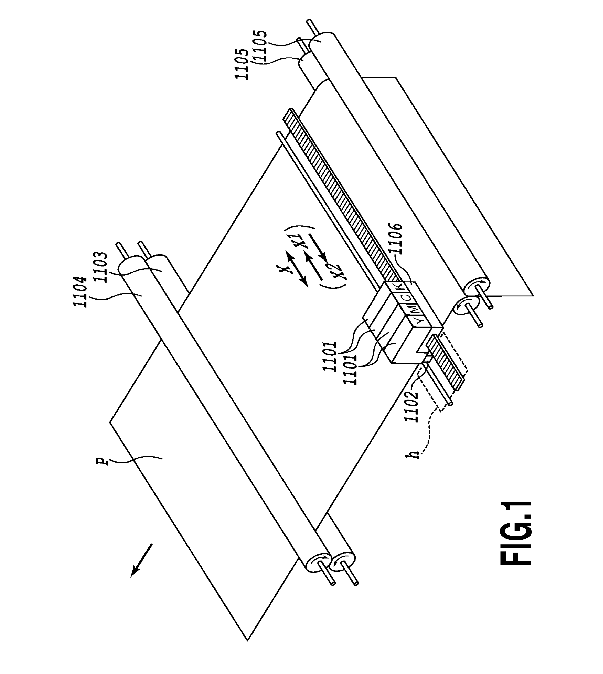
[0049]FIG. 1 is a perspective view of an essential part of a serial scan type ink jet printing apparatus to which the present invention is applicable.

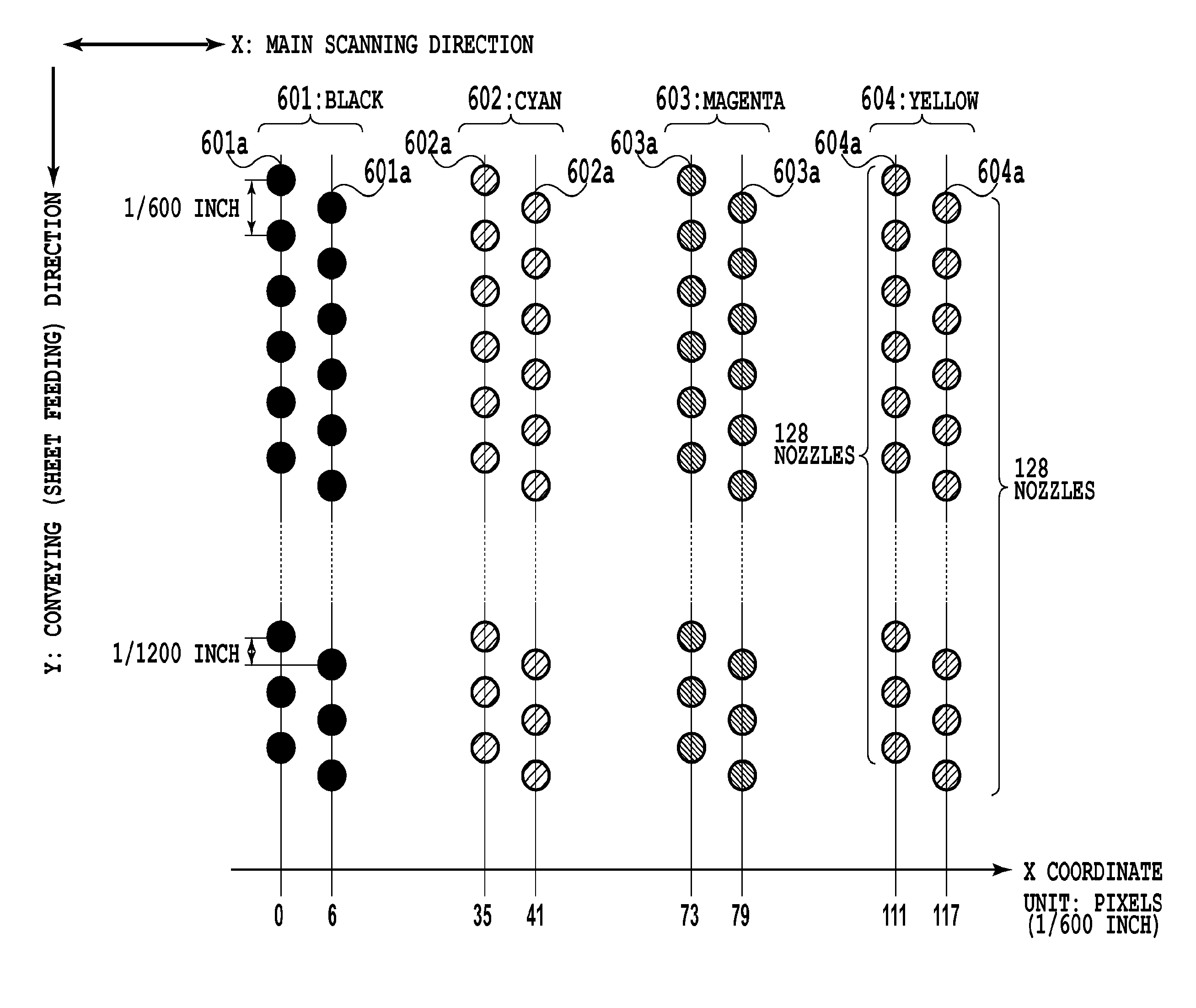
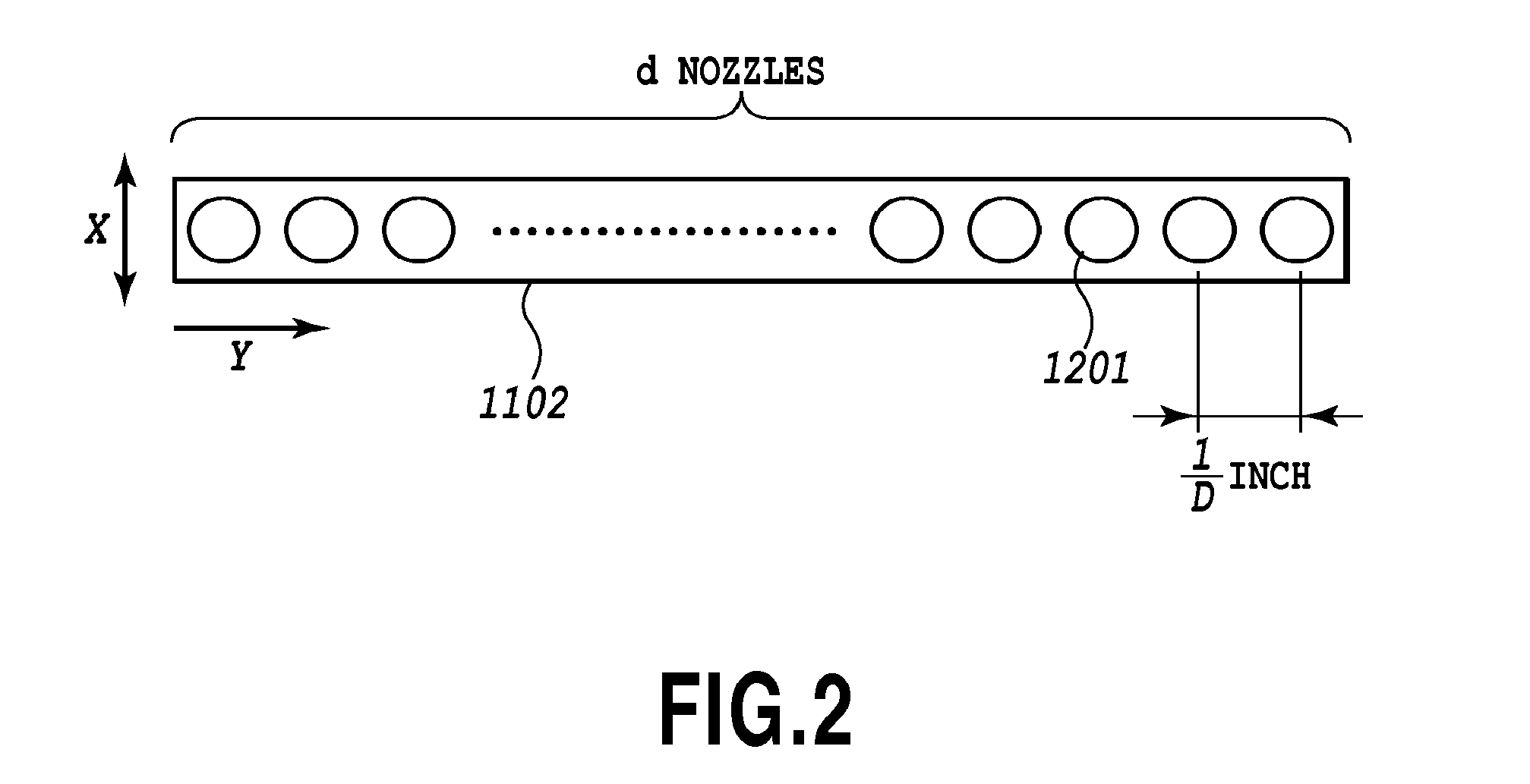
[0050]In FIG. 1, reference numeral 1101 denotes each of four ink jet cartridges. Each of the ink jet cartridges 1101 is composed of an ink tank in which a corresponding one of four color inks, that is, black ink, cyan ink, magenta ink, and yellow ink is stored, and a print head 1102 corresponding to the ink. FIG. 2 is a schematic diagram of ejection ports (hereinafter referred to as “nozzles”) 1201 for one color disposed on one print head 1102 as viewed from a print medium P. The print head 1102 has d ejection ports 1201 arranged thereon at a nozzle density (Ddpi) of D nozzles per inch. The print head 1102 can eject ink using electrothermal converter (heater) or piezo element. When the electrothermal converter is used, heat from the electrothermal converter is used to bubble the ink so that the resulting bubbling energy is utilized to ...

second embodiment

[0107]FIGS. 20 to 28 are diagrams illustrating a second embodiment of the present invention.

[0108]To increase print resolution, a print head in the present example has not only the nozzle rows for the respective ink colors in the print head according to the above-described embodiment in FIG. 6 but also nozzle rows arranged in a staggered pattern providing a smaller ink ejection amount.

[0109]As shown in FIG. 20, nozzle rows 601c and 601d are added to the black ink ejecting nozzle rows 601a and 601b. As shown in FIG. 21, the ejection ports in the inner even-numbered nozzle row 601a and odd-numbered nozzle row 601b, arranged closer to a common ink supply path F, are in communication with the ink supply path F through channels Fa and Fb. The ejection ports in the outer odd-numbered nozzle row 601c and even-numbered nozzle row 601d, arranged further from the ink supply path F, are in communication with the ink supply path F through channels Fc and Fd. The ejection ports in the nozzle row...

third embodiment

[0137]In the first embodiment, the mask patterns are offset according to the physical positional displacement of the nozzle rows in the main scanning direction. In contrast, the present embodiment is characterized by offsetting the mask patterns according to print position adjustment values for the nozzle rows. The configuration of the print head according to the present embodiment is the same as that according to the first embodiment, shown in FIG. 6.

[0138]In the ink jet printing apparatus, dots printed using a certain nozzle row may be displaced from dots printed using a different nozzle row (print position displacement) resulting in image defects such as stripes or density unevenness. Thus, to adjust the print position displacement, the present embodiment controllably prints a plurality of patterns on the print medium, determines an adjustment value from, for example, density information obtained from the printed patterns, and on the basis of the adjustment value, adjusts the tim...


PUM


Abstract

The present invention provides an ink jet printing apparatus and an ink jet printing method which are based on the multi-pass printing method using a print head having a plurality of nozzle rows and which enables a reduction in the number of nozzles to be simultaneously driven, allowing ink to be stably ejected. On the basis of the multi-pass printing method of dividing print data into a plurality of pieces by using mask patterns, the mask patterns are offset according to the positional relationship between the plurality of nozzle rows in the print head.

Description

BACKGROUND OF THE INVENTION[0001]1. Field of the Invention[0002]The present invention relates to what is called a serial scan type inkjet printing apparatus that prints images using a print head that can eject ink, and a relevant ink jet printing method.[0003]2. Description of the Related Art[0004]A printing apparatus based on an ink jet method (hereinafter referred to as an “ink jet printing apparatus”) ejects ink from a print head onto a print medium for printing. The ink jet method allows definition to be increased more easily than the other printing methods. Furthermore, the ink jet printing apparatus advantageously operates fast and silently and is inexpensive. In particular, a demand for color image printing has recently been increasing, and ink jet printing apparatuses have been developed which can print high-quality images that are comparable to silver photographs. These printing apparatuses use a print head having a plurality of nozzles integrally arranged therein in order ...

Claims


Application Information

Patent Timeline
Patent Type & Authority Applications(United States)
IPC IPC(8): B41J2/145
CPCG03G15/104B41J2/145G03G2215/0658
Inventor TESHIGAWARA, MINORUTAKAHASHI, KIICHIROEDAMURA, TETSUYAMARU, AKIKOMURAYAMA, YOSHIAKINAKANO, TAKATOSHITAIRA, HIROSHI
Owner CANON KK
Why Eureka
Try Eureka