
Video device and adjusting mechanism thereof

a technology of adjusting mechanism and video device, which is applied in the direction of color television details, television systems, stands/trestles, etc., can solve the problems of lens module shaking or losing focus, fixing component structure, and lens module shooting angle easily deviating by gravity

Inactive Publication Date: 2013-09-19
VIVOTEK INC
View PDF11 Cites 5 Cited by
  • Summary
  • Abstract
  • Description
  • Claims
  • Application Information

AI Technical Summary

Benefits of technology

The patent text describes the problem of adjusting the shooting angle of a video device using hands. The issue is that the fixing component of the video device may not fix the shooting angle, resulting in shaking or loss of focus. Additionally, the shooting angle may easily be deviated by gravity over time, and the structure of the fixing component may be damaged by inappropriate force. This results in a fixed surveillance camera that cannot monitor the desired field of view and increases maintenance cost.

Problems solved by technology

Furthermore, a dome-shape casing covers the video device in order to prevent the video device from exposure, which causes damage.
However, in these approaches for adjusting the shooting angle of the lens module by hands, when the shooting angle of the video device is adjusted, a fixing component of the video device may cause the lens module to shake or lose focus because the fixing and clamping of the fixing component is weak.
Moreover, the shooting angle of the lens module may easily be deviated by gravity as time goes by.
When the video device is pressed by hands, the structure of the fixing component may be damaged by inappropriate force, such that the fixing component may lose the function of fixing the shooting angle of the video device, and the user may not adjust the desired shooting angle of the video device.
Therefore, in the fixed surveillance camera, because the shooting angle of the video device is adjusted by hands, the fixing component may not fix the shooting angle of the video device, such that the fixed surveillance camera may not monitor the desired field of view and the maintenance cost is increased.

Method used


Image

  • Video device and adjusting mechanism thereof
  • Video device and adjusting mechanism thereof
  • Video device and adjusting mechanism thereof

Examples


Embodiment Construction

[0015]In the following detailed description, for purposes of explanation, numerous specific details are set forth in order to provide a thorough understanding of the disclosed embodiments. It will be apparent, however, that one or more embodiments may be practiced without these specific details. In other instances, well-known structures and devices are schematically shown in order to simplify the drawing.

[0016]The disclosure provides an adjusting mechanism applicable for fixing a video module. By means of rotating the adjusting mechanism, the video module is driven to rotate (namely, spin) accordingly.

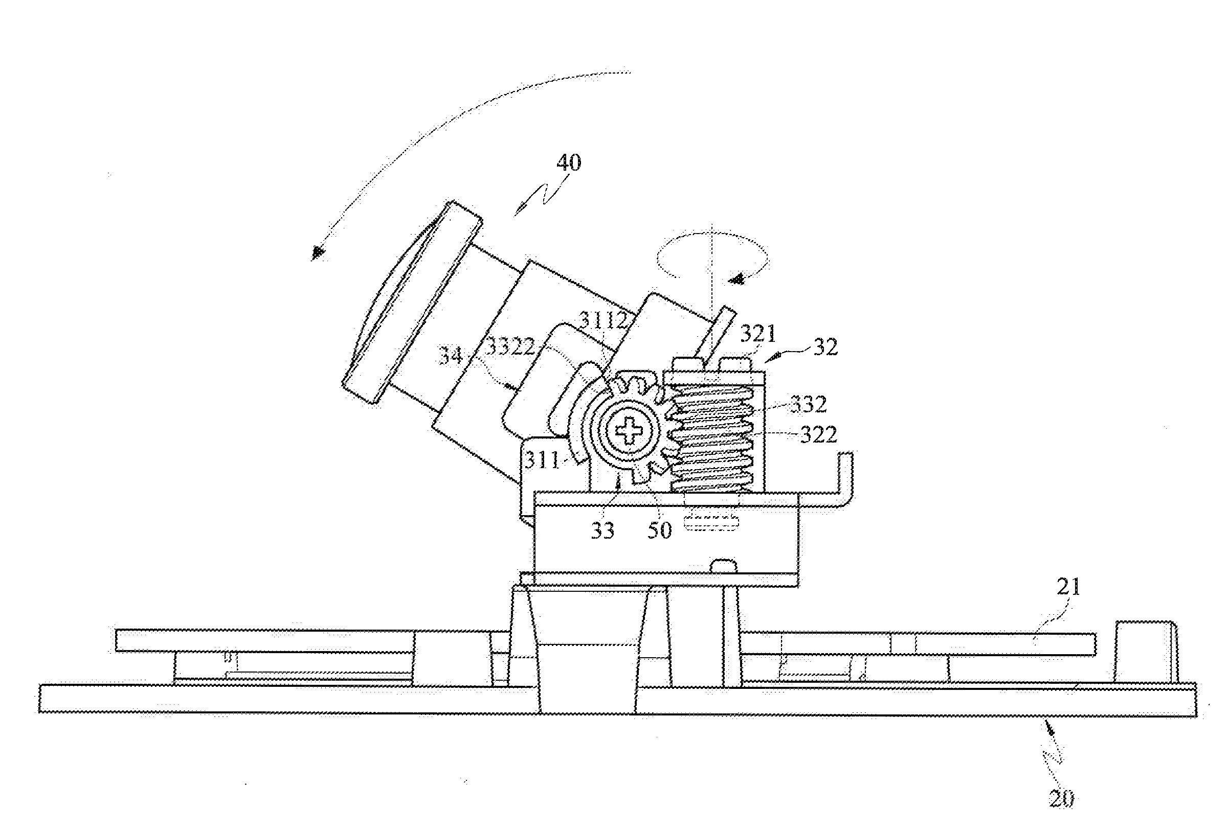
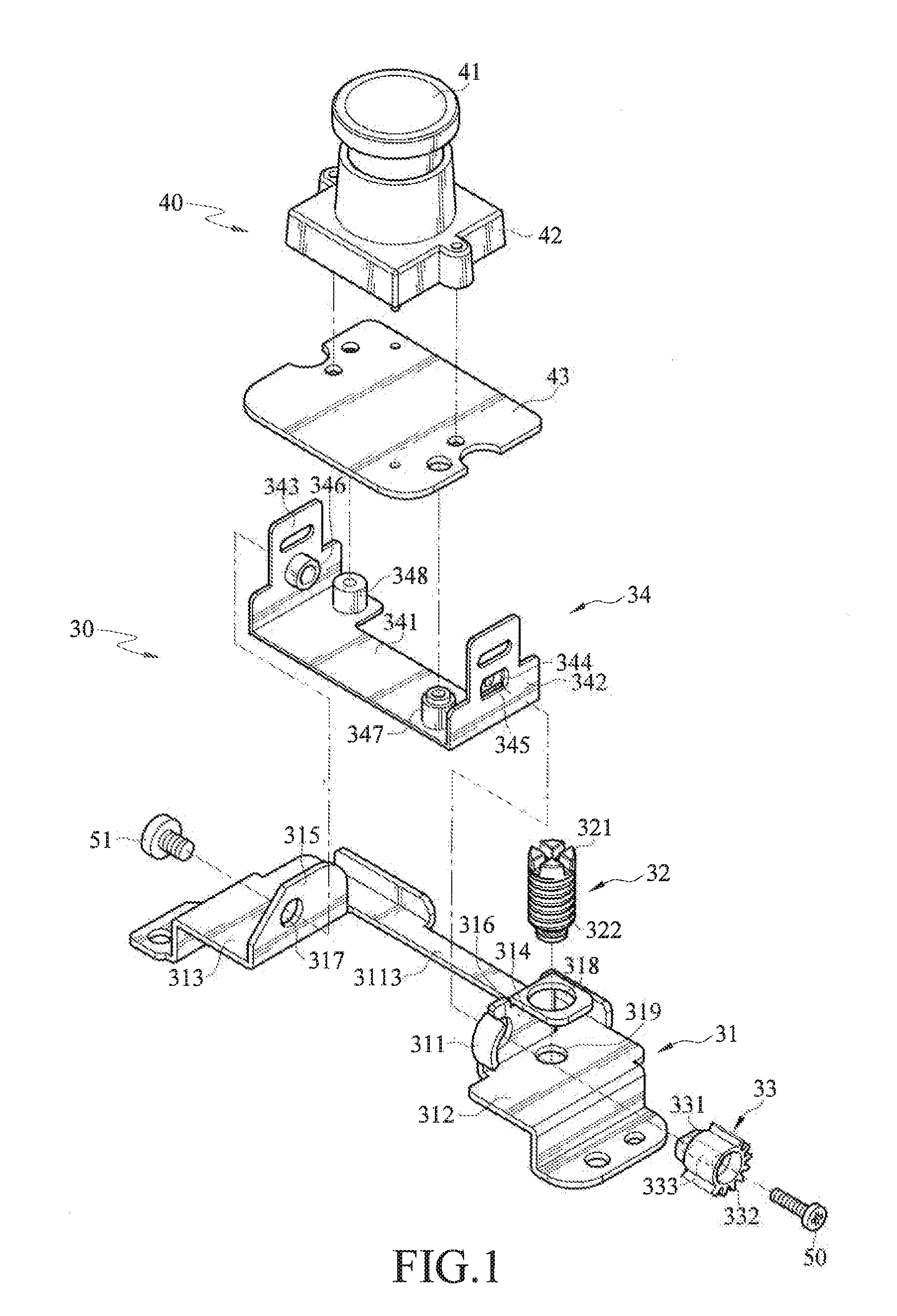
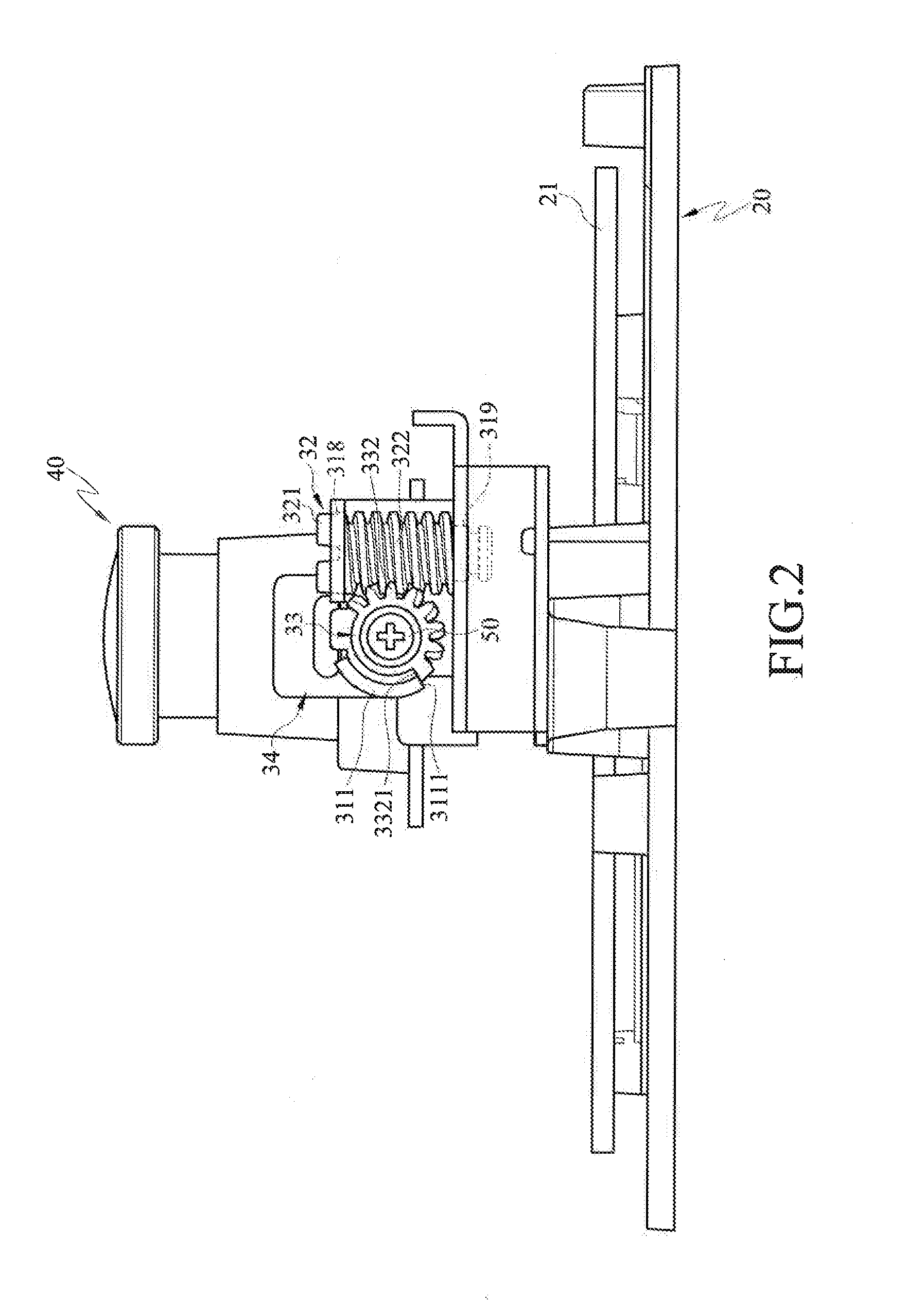
[0017]The following describes an adjusting mechanism according to an embodiment of the disclosure. Please refer to FIGS. 1 and 2, FIG. 1 is an exploded view of an adjusting mechanism according to an embodiment of the disclosure, and FIG. 2 is a first side view of the adjusting mechanism according to an embodiment of the disclosure.

[0018]The adjusting mechanism 30 comprises a fixing bra...


PUM


Abstract

An adjusting mechanism, applicable for a video device, includes a fixing bracket, an adjusting component, a linking component and a rotating bracket. The adjusting component is disposed on a side of the fixing bracket. The linking component is engaged with the adjusting component. The rotating bracket is connected to the linking component and is pivoted to the fixing bracket. When the adjusting component is rotated by an external force, the linking component drives the rotating bracket to pivot relative to the fixing bracket.

Description

CROSS-REFERENCE TO RELATED APPLICATIONS[0001]This non-provisional application claims priority under 35 U.S.C. §119(a) on Patent Application No(s). 101204759 filed in Taiwan, R.O.C. on Mar. 15, 2012, the entire contents of which are hereby incorporated by reference.TECHNICAL FIELD[0002]The disclosure relates to a video device and an adjusting mechanism thereof, and more particularly to a fixed video device and an adjusting mechanism thereof.BACKGROUND[0003]No matter at homes, enterprises, governments or public places, a surveillance camera plays important role on human security and asset protection. Typically, the surveillance camera comprises a video device for monitoring the condition of a certain monitored environment such that unexpected invasions and occurrences of special circumstances may be detected, and therefore user may be informed immediately so as to handle the events. The conventional surveillance camera has two types which are fixed surveillance camera and rotary surve...

Claims


Application Information

Patent Timeline
IPC IPC(8): H04N5/225
CPCH04N5/2251F16M11/18F16M11/10
Inventor HUANG, SHANG-YU
Owner VIVOTEK INC
Learn More