Transient impedance transformer based on ac voltage regulating electronic switch

Inactive Publication Date: 2016-12-08
SUN CHONGSHAN
View PDF1 Cites 26 Cited by
  • Summary
  • Abstract
  • Description
  • Claims
  • Application Information

AI Technical Summary

Problems solved by technology

UHV AC transmission has disadvantages of higher voltage, long transmission lines, large distribution capacity, small wave impedance, obvious fault wave process.
Secondly, the DC power transmission has limit on short-circuit current.
However, when the DC power transmission line is used for connecting two AC systems, the “constant current control” of the DC system limits the short-circuit current near rated power, and thus the capacity of short circuit is not increased due to interconnection.
Thirdly, there is no capacitor charging current.
The existing electrolytic silicon rectifier units are not silicon controlled units due to power factors, and barely provided with saturated reactor.
However, the loaded tap switches have slow operation speed, and thus may not amend momentary fluctuation of the electrolytic current, such as, when anode effect occurs in aluminum electrolysis (depend on the difference line voltages, line current may be decreased by 5-10% which lasts for several minutes).
If the tap switches are utilized for elevating voltage to maintain the series current, when the anode effect does not exist, current impact will occur due to lower operation speed of the tap switches.
Thus, this transitory variation of current is typically not regulated.
In addition, in order to reduce the times of operation for the loaded tap switches, it is impossible to respond to transitory variation of current.
However, it is very difficult to achieve the above accuracy only by utilizing the loaded tap switches in the system.
The operations of the loaded tap switches are very slow with respect to the response for current modulation system.
However, the variation time for voltage regulation of the loaded switch is 10 s to 20 s, when the range of voltage regulation is large, the response time will fail to follow up with the variation time of current.
In the melting period, due to direct arc between steel scrap and electrodes, as the steel scrap melts, the length of the arc will certainly change, thereby causing movement of the arcing points, and the electrode controlling system cannot follow up with saltatory variation of the arc and cannot compensate timely due to mechanical inertia response time within several seconds to ten or more seconds, and thus the arc is not stable.
At th

Method used


Image

  • Transient impedance transformer based on ac voltage regulating electronic switch
  • Transient impedance transformer based on ac voltage regulating electronic switch
  • Transient impedance transformer based on ac voltage regulating electronic switch

Examples


example 1

[0157]In the present solution, the AC voltage regulating electronic switch is not used, but a new AC voltage regulator is used, which is aimed at showing the capability of voltage regulation of the AC voltage regulator under extreme cases. A furnace, resistance-inductive load, is provided, when the distance from the electrode to the burden surface is determined, the maximal and minimal output voltages of the series voltage regulating transformer is required to be between 1 and 0.7, respectively.

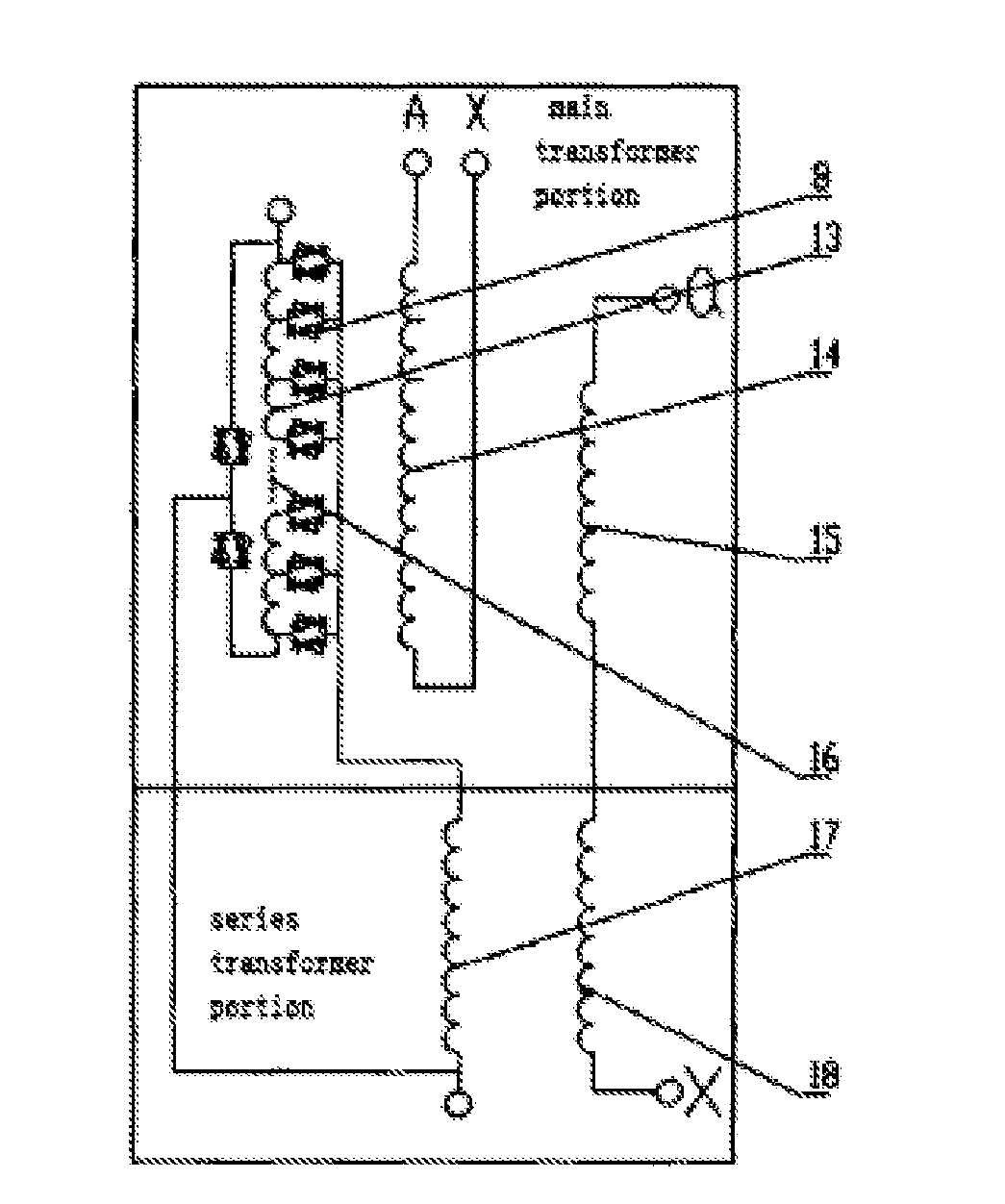
[0158]A furnace transformer, three phases, is provided, and a series voltage regulating transformer, with range of voltage regulation of 30% and positive voltage regulation, is also provided, the main transformer and the series transformer are of an Yd11 connection group. The output constant voltage at lower voltage of the main transformer is U1=0.7, and the highest output voltage at lower voltage of the series transformer is U2=0.3. The high voltage and current of the series transformer can ...

example 2

[0161]A furnace transformer with range of voltage regulation of 40%, reversing change-over voltage regulating, Yd11 connection group, and a series voltage regulating transformer are provided. The secondary winding of the main transformer is connected, in parallel, to the capacitor group to adjust the power factor. Before compensation, cos φ=0.8, it is required that after compensation, cos φ=0.95. The principle of electrical wiring is showed by the combination form of the low-voltage winding and the reactive compensation device, as showed in FIG. 16. U21 and U22 are secondary voltages of the main transformer, and series transformer, respectively, and the leakage reactance of the transformer is omitted. FIG. 17 is a vectogram showing the current before compensation. Before compensation, the power factor is defined as cos φ=0.8, sin φ=0.6, and meanwhile, the working current of the furnace IL=1. The active component of the working current is IR=0.8. The idle component of the working cur...

example 3

[0167]A furnace transformer with range of voltage regulation of 40%, reversing change-over voltage regulating, Yd11 connection group, and a series voltage regulating transformer are provided. The low voltage of the main transformer is 0.8, the low voltage of the series transformer is 0˜0.2, the combined voltage of the main and series transformers is 0.8±(0˜0.2), with 21 levels of voltage regulation, each of which is 0.02, the capacity of the main transformer is 0.4˜1, and the tolerance of each level of the main transformer is 0.03. It is assumed that the ratio of transformation is 1, and the resistance values of the two windings of the low-voltage main and series transformers are the same. It is assumed that the working current of the furnace after compensation is still IL=1, and the current of the secondary winding of the main transformer is I21=0.842, and the no-load loss is about of 15% of the load loss.

[0168]As showed in Example 2: loss of the transformer Pk is

Pk=(0.842 IL)2×0.8...


PUM


Abstract

A superposition principle of waveform based on conceptions of waveform continuity and flexible regulation of voltage proposes three concepts, respectively being flexible AC transformation, flexible power transmission and transformation and flexible voltage regulation; proposes three new technologies, respectively being a transient impedance technology, a flexible stepless voltage regulation technology and a flexible stepped voltage regulation technology; proposes three new products, being an AC voltage regulating electronic switch, a transient impedance transformer and a high-speed voltage regulating transformer; proposes six high-voltage power grid connection methods, being a power grid connection method type of a transient impedance transformer, a power grid connection method of a transient impedance step up auto transformer and the like; and proposes a new reactive compensation connection method for a reactive compensation device.

Description

RELATED APPLICATIONS[0001]The present application is a National Phase of International Application Number PCT / CN2014 / 071434, filed Jan. 25, 2014, and claims the priority of China Application No. 201410034576.X, filed Jan. 25, 2014, which are incorporated herein by reference in their entireties.FIELD OF THE INVENTION[0002]The present invention specifically describes a development of conceptions, and proposes three concepts, three new technologies, three new products, six high-voltage power grid connection methods, a new type of reactive compensation connection method, proposes a new solution to usage of AC voltage regulator. The present invention relates to the technical fields of power electronics, transformer, high voltage or ultra-high voltage power grid transmissions, stepless voltage regulation technology, reactive compensation technology.[0003]The above development of the conceptions direct to a superposition principle of waveform based on conceptions of waveform continuity and...

Claims


Application Information

Patent Timeline
IPC IPC(8): H02J3/18H02J50/10H02J3/10
CPCH02J3/1878H02J50/10H02J3/10H02J3/36Y02E40/30Y02E60/60H02J3/12H02P13/06
Inventor SUN, CHONGSHAN
Owner SUN CHONGSHAN
Why Eureka
Try Eureka