Two-shaft gas turbine

a gas turbine and shaft technology, applied in the direction of machines/engines, mechanical equipment, separation processes, etc., can solve the problems of increased output power, blade vibration and shaft vibration, excessive rotation of compressors, etc., to improve efficiency, enhance reliability, and stable operation

Active Publication Date: 2009-12-31
MITSUBISHI POWER LTD
View PDF6 Cites 38 Cited by
  • Summary
  • Abstract
  • Description
  • Claims
  • Application Information

AI Technical Summary

Benefits of technology

[0009]As a measure of preventing the excessive rotation of the compressor, a method is conceivable of reducing a flow rate of fuel supplied to a combustor to control the rotation speed of the compressor into a given value. If this method is adopted, however, the turbine inlet temperature drops to lower the efficiency of the gas turbine. This will lower an efficiency-improving effect which is an original aim of the humidity gas turbine system.
[0010]As a second measure of preventing the excessive rotation of the compressor, a method is conceivable of mechanically previously setting the output power of the high-pressure turbine and of the low-pressure turbine so as to optimize the load distribution therebetween in humidifying compressed air.
[0012]The same problem as described above is shared by a gas turbine system in which the flow rate of working fluid supplied to a combustor is increased compared with the simple cycle gas turbine. The following gas turbine system can be conceivable as an example of such a gas turbine system. Extra steam is injected into the combustor of the gas turbine to improve efficiency in a combined cycle gas turbine system or a cogeneration system in which heat of the exhaust gas of the gas turbine is used to produce steam for use. In a plant equipped with an air separation system, the same problem occurs in a gas turbine system in which extra nitrogen is injected into a gas turbine combustor to increase output power and to reduce NOx. A low-calorific fuel-firing gas turbine system needs to burn a large quantity of fuel compared with the simple cycle gas turbine so that the flow rate of working fluid increases accordingly. This poses the same problem as above if the low-calorific fuel-firing gas turbine system is applied to the two-shaft gas turbine.
[0013]It is an object of the present invention, therefore, to provide a two-shaft gas turbine with improved reliability that improves output power and efficiency and is stably operated by establishing a balance between the driving force of a compressor and the output power of a high-pressure turbine in the case where the two-shaft gas turbine is applied to such a system that the flow rate of fluid flowing into a combustor is increased compared with a simple cycle gas turbine.
[0015]The present invention can achieve a two-shaft gas turbine that can improve efficiency and establish a balance between the driving force of a compressor and the output power of a high-pressure turbine, thereby providing stable operation and enhanced reliability.

Problems solved by technology

However, if the technology of the humidity gas turbine system is applied to a two-shaft gas turbine, the humidification will increase the output power of a high-pressure turbine driving a compressor.
In this case, the compressor will excessively be rotated if nothing is done.
The excessive rotation of the compressor will cause the blade vibration and shaft vibration of the compressor and of the high-pressure turbine.
Since it is probable that sympathetic vibration with such vibrations may damage rotary components, it is not preferred to excessively rotate the compressor.
If this method is adopted, however, the turbine inlet temperature drops to lower the efficiency of the gas turbine.
This will lower an efficiency-improving effect which is an original aim of the humidity gas turbine system.
If this method is adopted, however, the output power of the high-pressure turbine becomes smaller than power needed to drive the compressor.
When compressed air is not humidified, such as when the gas turbine is started, the compressor will be rotated at excessively low rotation speed.
This leads to damage to the rotary components.
In addition, this undesirably leads to a reduction in the flow rate and pressure ratio of the gas turbine working fluid as well as to lowering in the compression efficiency thereof.
That is to say, the turbine blades cannot be shared by the simple cycle and the humid air gas turbine; therefore, they are increased in production cost.

Method used


Image

  • Two-shaft gas turbine
  • Two-shaft gas turbine
  • Two-shaft gas turbine

Examples


first embodiment

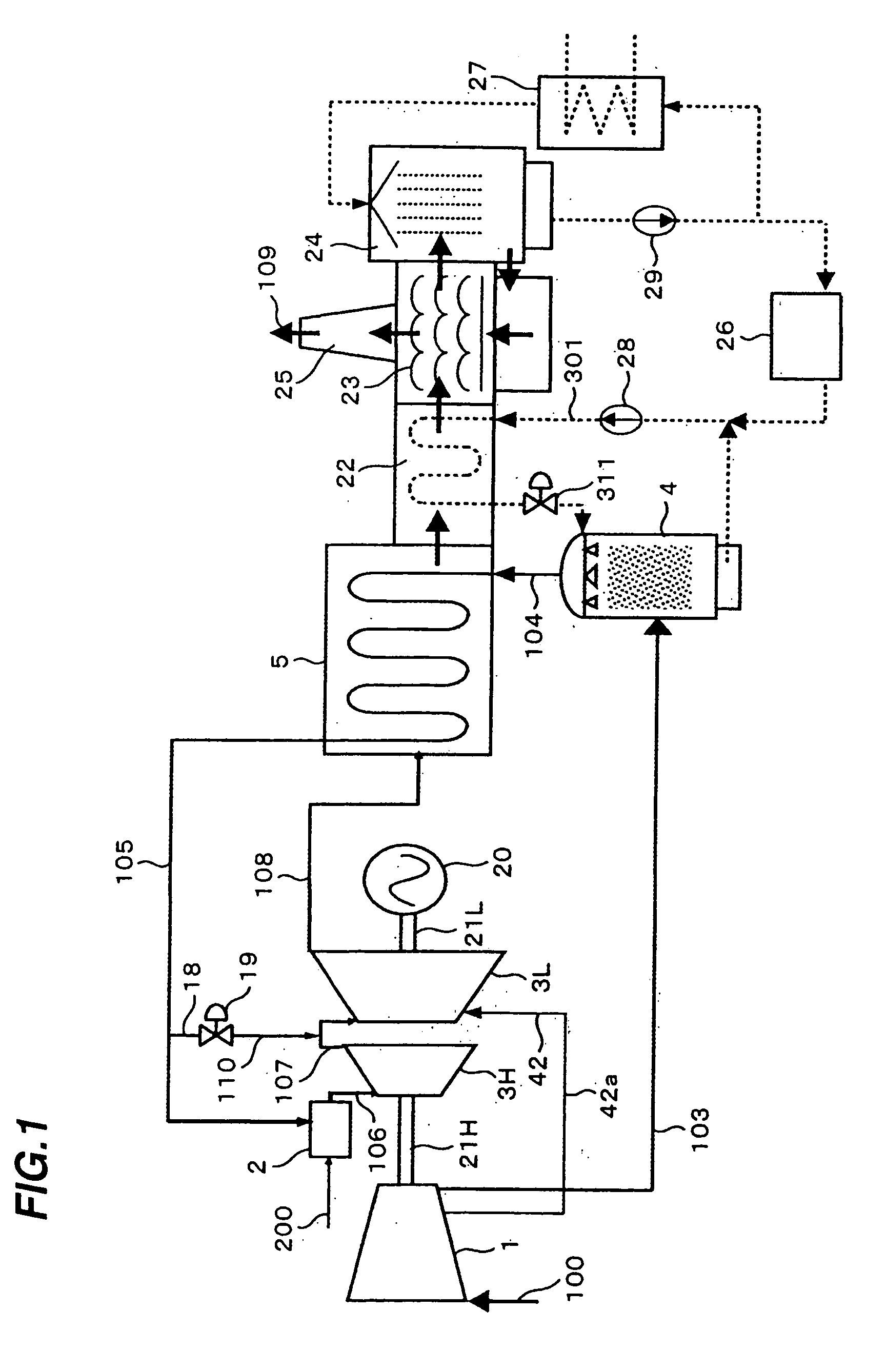
[0038]A description is given of a first embodiment of a two-shaft gas turbine system in which the present invention is applied to a humidity gas turbine system with reference to FIG. 1.

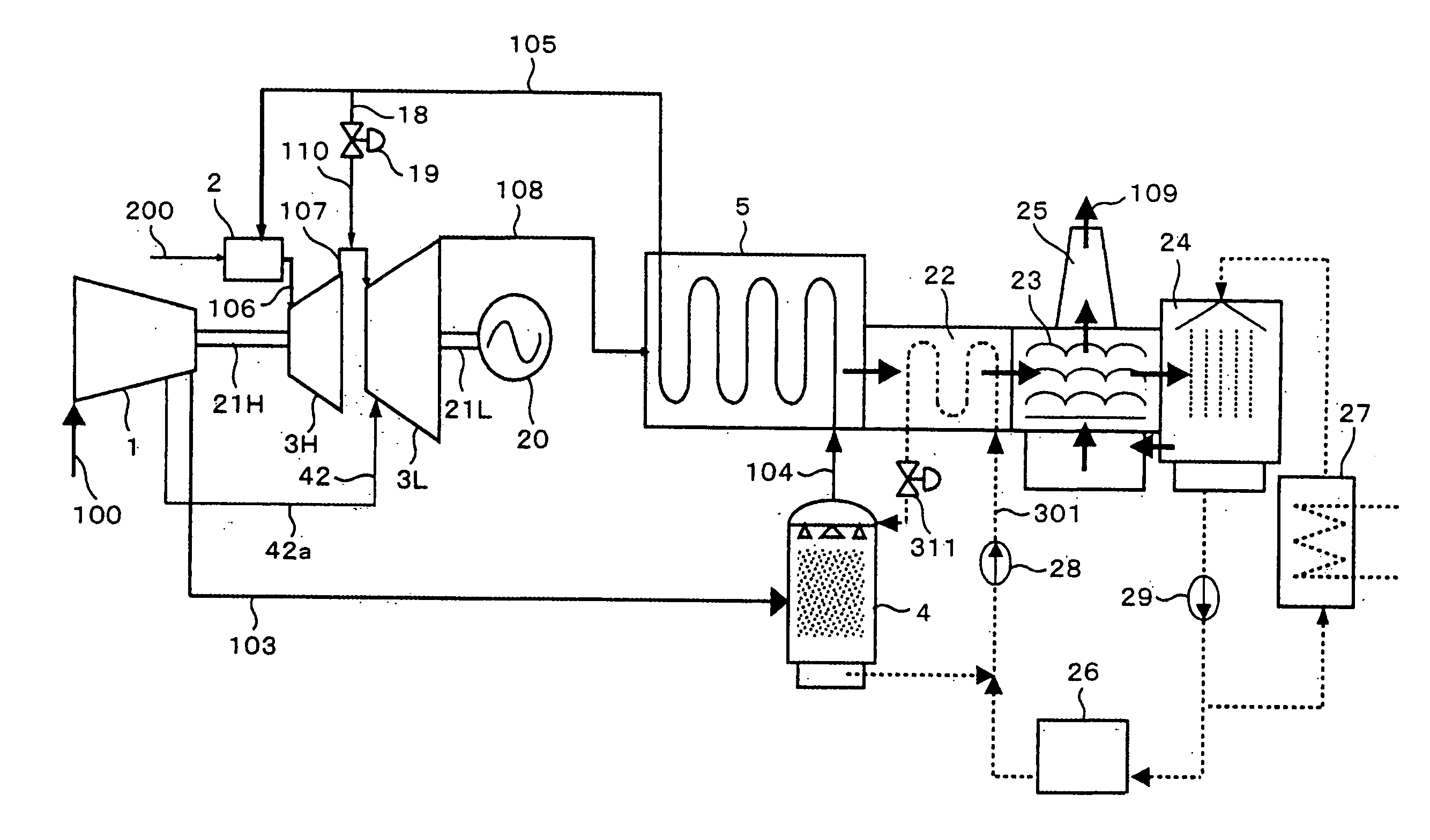
[0039]FIG. 1 is a system flow diagram illustrating an overall configuration of the two-shaft gas turbine constituting part of the humidity gas turbine system according to the first embodiment of the present invention.

[0040]Referring to FIG. 1, the two-shaft gas turbine installed in the humidity gas turbine system for power generation includes a compressor 1, a combustor 2, a high-pressure turbine 3H, a low-pressure turbine 3L, a humidifier 4, and a recuperator 5. The compressor 1 compresses air to produce high-pressure air. The combustor 2 is adapted to mix supplied fuel 200 with combustion air to produce high-temperature combustion gas. The high-pressure turbine 3H is driven by the high-temperature combustion gas produced by the combustor 2. The low-pressure turbine 3L is driven by the high-pressure ...

second embodiment

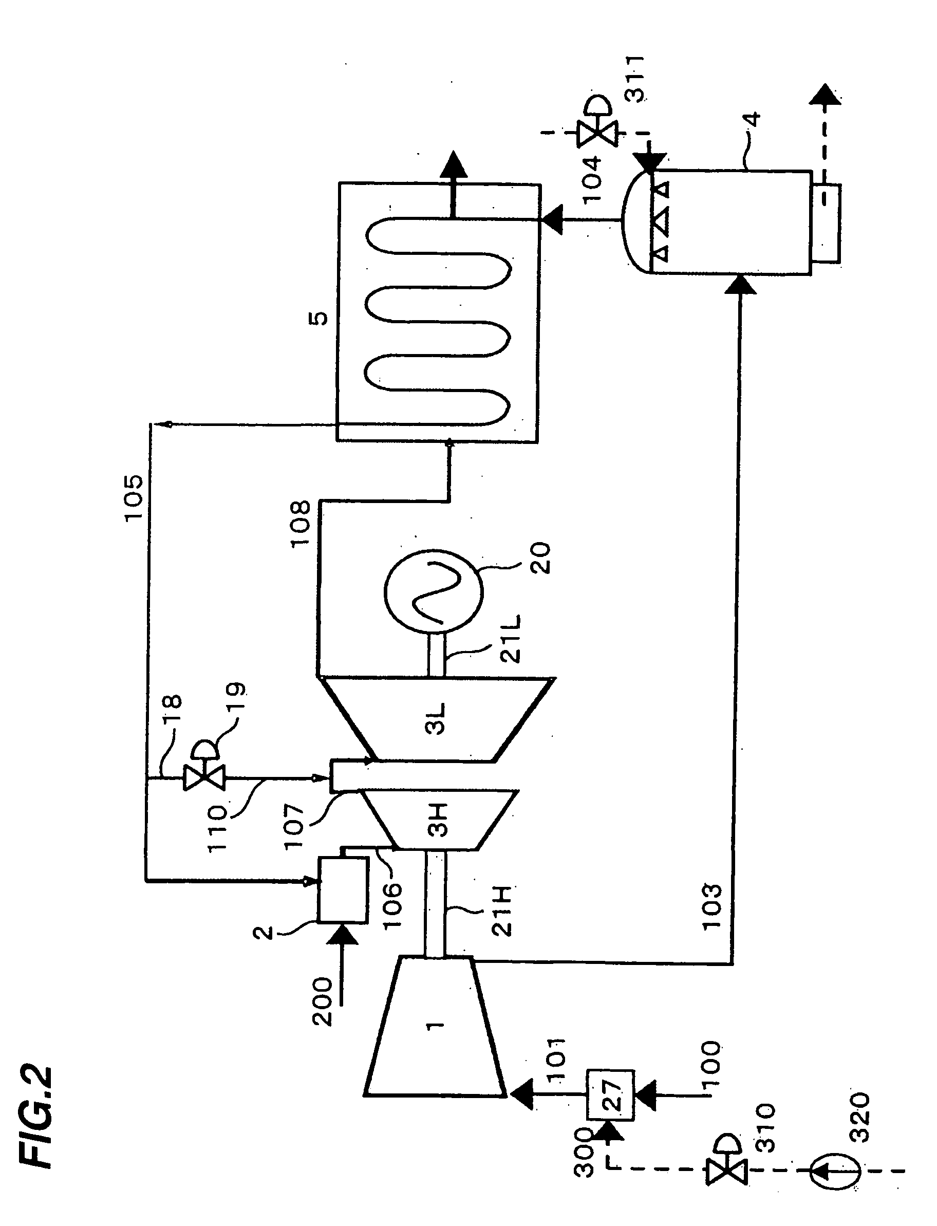
[0094]FIG. 2 illustrates a second embodiment of the present invention, in which the exhaust gas system downstream of the recuperator 5 common to FIG. 1 is omitted.

[0095]The second embodiment of FIG. 2 is different from the first embodiment illustrated in FIG. 1 in that a water atomization cooling system 27 is provided at a suction air inlet of the compressor 1 to spray fine water drops for evaporation to lower the temperature of the working fluid in the compressor.

[0096]In the water atomization cooling system 27, atomized water 300 to be sprayed into the compressor inlet air 100 at the inlet of the compressor 1 is pressurized by a high-pressure pump 320. Then, the pressurized atomized water 300 is adjusted to a given flow rate by an atomized water volume control valve 310 and miniaturized by an atomizing nozzle in the water atomization cooling system 27. A portion of the miniaturized water drops is evaporated before sucked into the compressor to lower the temperature of the working ...

third embodiment

[0106]FIG. 3 illustrates a third embodiment of the present invention, in which the exhaust gas system downstream of the recuperator 5 is omitted similarly to FIG. 2.

[0107]The third embodiment of FIG. 3 is different from the second embodiment illustrated in FIG. 2 in that a compressor 1b (a solid line) is used which is manufactured to reduce the flow rate of working fluid of the compressor 1 indicated with a dotted line in FIG. 3. The compressor of the present embodiment can easily be manufactured by the manufacturing method disclosed by e.g. JP-A-2005-155613 because parts and drawings can be shared by the gas turbine compressor 1 designed for the simple cycle illustrated in FIG. 2.

[0108]Since the compressor 1b of the present embodiment is manufactured to reduce the flow rate of the working fluid compared with that of the simple cycle, also the compressor driving force can be reduced.

[0109]The effect of reducing the compressor driving force according to the present embodiment is here...


PUM

PropertyMeasurementUnit
humidityaaaaaaaaaa
output poweraaaaaaaaaa
pressureaaaaaaaaaa

Abstract

Provided is a two-shaft gas turbine with improved reliability that improves output power and efficiency and is stably operated by establishing a balance between the driving force of a compressor and the output power of a high-pressure turbine in the case where the two-shaft gas turbine is applied to a system in which the flow rate of fluid flowing into a combustor is increased compared with a simple cycle gas turbine.A portion of working fluid driving the high-pressure turbine is allowed to flow not into the high-pressure turbine but into a low-pressure turbine.

Description

BACKGROUND OF THE INVENTION[0001]1. Field of the Invention[0002]The present invention relates to a two-shaft gas turbine in which a high-pressure turbine for driving a compressor and a low-pressure turbine for power output are configured to have respective different shafts. The two-shaft gas turbine is applied to a gas turbine system having an increased amount of fluid flowing into a combustor compared with a simple cycle, such as, e.g., a humid air system, a steam injection system, a nitrogen injection system, or a low-calorific fuel firing system.[0003]2. Description of the Related Art[0004]For example, JP-A-2003-83081 (FIG. 5) and JP-A-5-18271 describe the technology of a two-shaft gas turbine in which a high-pressure turbine for driving a compressor and a low-pressure turbine for driving a generator or a pump are configured to have respective different shafts.[0005]The two-shaft gas turbine can rotate the compressor and the high-pressure turbine at high speeds even if a driven d...

Claims


Application Information

Patent Timeline
Patent Type & Authority Applications(United States)
IPC IPC(8): F02G3/00
CPCF02C3/10Y02E20/16Y02E20/14F02C6/18F02C3/305F02C9/16F05D2260/15
Inventor KOGANEZAWA, TOMOMIHIGUCHI, SHINICHITAKAHASHI, YASUOAKIYAMA, RYOMARUSHIMA, SHINYA
Owner MITSUBISHI POWER LTD
Why Eureka
Try Eureka