
Test circuit adapted in a display panel of an electronic device

Active Publication Date: 2010-03-25
AU OPTRONICS (SUZHOU) CORP LTD +1
View PDF5 Cites 32 Cited by
  • Summary
  • Abstract
  • Description
  • Claims
  • Application Information

AI Technical Summary

Benefits of technology

[0007]Accordingly, what is needed is a test circuit to prevent the static electricity and lower the effect of the difference between the transistors to overcome the above issues. The present invention addresses such a need.

Problems solved by technology

Besides the design of the pixel array and the drive circuit in the display panel, the test circuit is also an important issue in the manufacturing process of the display panel.
The laser cut process raises the cost of the manufacturing process.
Further, if the laser cut process doesn't completely cut off the test signal lines, the connection of the test signal lines, pixel array and the drive circuit may cause abnormal display result.
However, the transistor may suffer from static electricity and further cause damage to the pixel array and the drive circuit.

Method used


Image

  • Test circuit adapted in a display panel of an electronic device
  • Test circuit adapted in a display panel of an electronic device
  • Test circuit adapted in a display panel of an electronic device

Examples


Embodiment Construction

[0017]Reference will now be made in detail to the present embodiments of the invention, examples of which are illustrated in the accompanying drawings. Wherever possible, the same reference numbers are used in the drawings and the description to refer to the same or like parts.

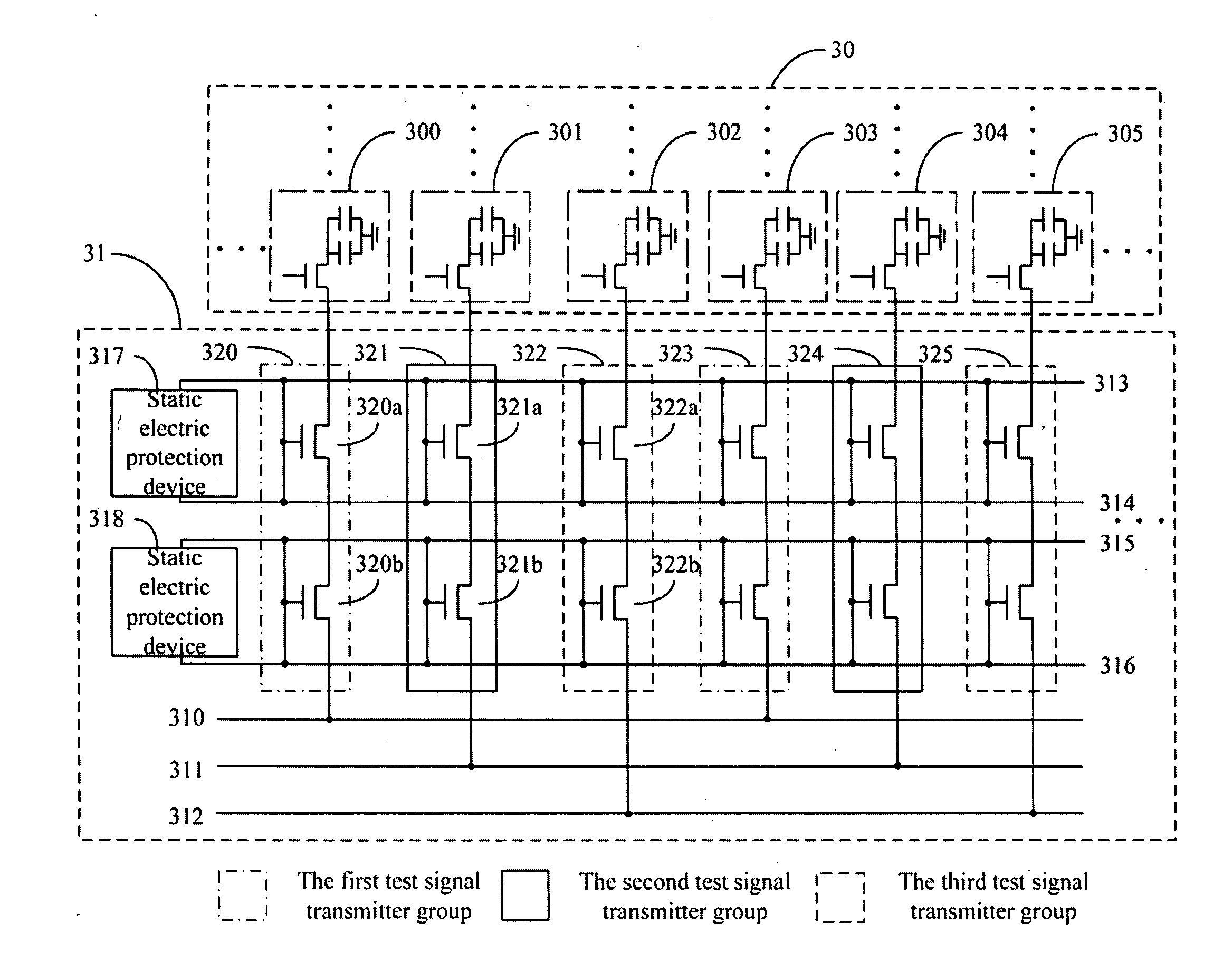
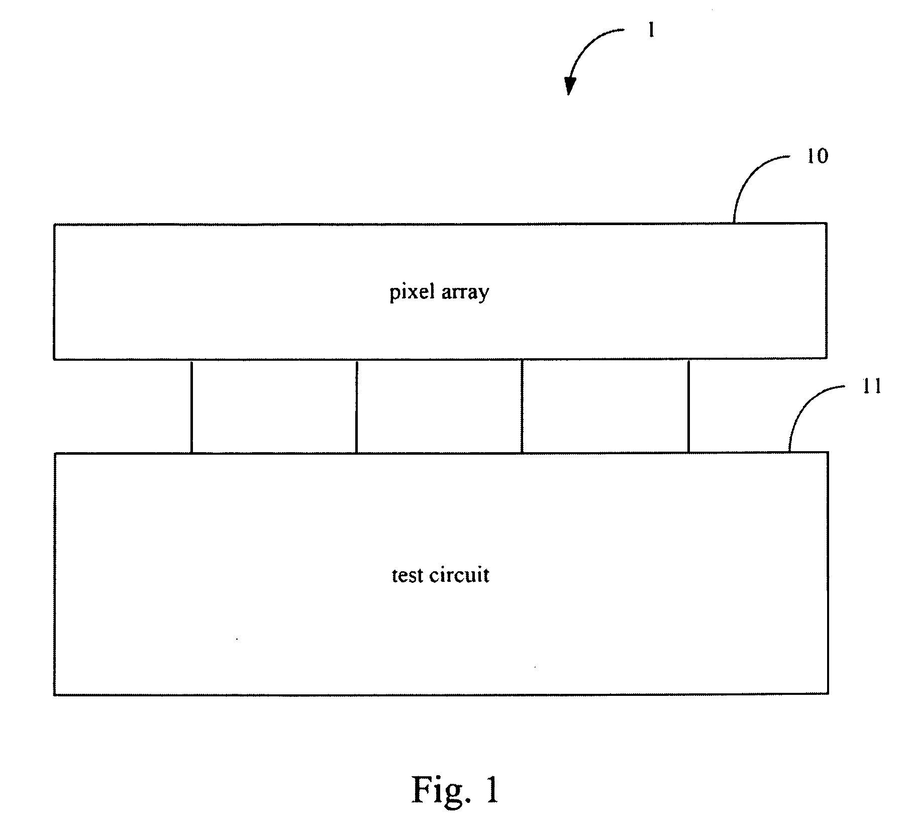
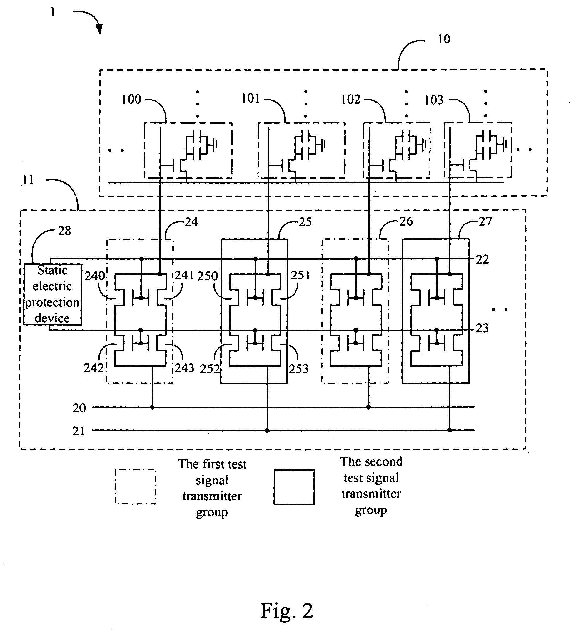
[0018]Please refer to FIG. 1. FIG. 1 is a block diagram of the display panel 1 of the first embodiment of the present invention. The display panel 1 is adapted in an electronic device (not shown), wherein the electronic device further comprises a host (not shown). The display panel 1 comprises a pixel array 10 and a test circuit 11. Please refer to FIG. 2 at the same time. FIG. 2 is a circuit diagram of the display panel 1 of the first embodiment of the present invention. The pixel array 10 comprises a plurality of pixels. In FIG. 2, only four pixels 100, 101, 102 and 103 are shown. The test circuit 11 comprises two test signal lines 20 and 21, a plurality of test signal transmitters, two gate lines 22 and 23 ...


PUM


Abstract

A test circuit adapted in a display panel of an electronic device is provided. The test circuit is to test the pixel array function of the display panel, wherein the test circuit comprises: a plurality of test signal lines, a plurality of test signal transmitters, a plurality of gate lines and at least one static electricity protection device. The test signal lines receive a plurality of corresponding test signals respectively. The test signal transmitters comprises a plurality test signal transmitter groups comprising at least one transmitter, wherein each transmitter group corresponds to a test signal line and connects the test signal line and the pixel array. Each gate line connects to the gate of the at least one transmitter. The static electricity protection device is placed between two of the gate lines.

Description

RELATED APPLICATIONS[0001]This application claims priority to China Application Serial Number 200810165782.9, filed Sep. 23, 2008, which is herein incorporated by reference.BACKGROUND[0002]1. Field of Invention[0003]The present invention relates to a test circuit. More particularly, the present invention relates to a test circuit to test the pixel array function of a display panel.[0004]2. Description of Related Art[0005]Display panels are extensively used as computer monitors, televisions and as screens for mobile devices, etc. Besides the design of the pixel array and the drive circuit in the display panel, the test circuit is also an important issue in the manufacturing process of the display panel. The test circuit tests the function without affecting the normal operation of the pixel array of the display panel.[0006]A conventional test circuit connects the test signal lines directly to the pixel array and the drive circuit. After the test process, a laser cut process is perform...

Claims


Application Information

Patent Timeline
IPC IPC(8): G01R31/02
CPCG09G2330/04G09G3/006
Inventor WANG, XIAO-LINLIU, TING-TINGXI, JIE
Owner AU OPTRONICS (SUZHOU) CORP LTD
Learn More