Supporting substrate for manufacturing flexible informaiton display device using temporary bonding/debonding layer, manufacturing method thereof, and flexible information display device

a technology of flexible information display and supporting substrate, which is applied in the direction of record information storage, instruments, transportation and packaging, etc., can solve the problems of deformation of the precise alignment between the masks used for the process, easy damage to glass substrate, and high equipment cost, so as to reduce the investment cost of manufacturing the device. , the effect of high maintenance cos

Inactive Publication Date: 2015-03-05
LEE KEUN SOO +2
View PDF2 Cites 29 Cited by
  • Summary
  • Abstract
  • Description
  • Claims
  • Application Information

AI Technical Summary

Benefits of technology

[0016]Accordingly, the present invention has been made keeping in mind the above problems occurring when a flexible flat panel information display is manufactured using the temporary bonding / debonding process in the prior art, and an object of the present invention is to provide a supporting substrate including a temporary bonding / debonding layer capable of being easily separated without deforming the flexible information display device or damaging the device when debonding the flexible substrate on which the information display device is formed from the supporting substrate. During a manufacturing process, precision of the process is improved by minimizing the size variation of the flexible substrate so that an information display device having high resolution may be manufactured. When debonding the flexible flat panel information display device from the glass supporting substrate, deformation and damage of the device are minimized so that the information display device having high resolution may be economically manufactured.
[0031]First, according to the manufacturing method of the present invention, an investment cost of a manufacturing device is significantly reduced. That is, since the flexible flat panel information display device is debonded from the glass supporting substrate by a mechanical scheme, there is no need for a facility having a high equipment cost and a high maintenance cost.
[0032]Secondly, according to the manufacturing process according to the present invention, since defects of the flexible flat panel information display is minimized so that the flexible flat panel information display may be debonded from the glass supporting substrate, a yield rate of the manufacturing process is improved and accordingly an economy of the manufacturing process will be reviewed.
[0033]Finally, according to the manufacturing process of the present invention, since modification of a parallel direction of the flexible substrate formed on the glass supporting substrate is minimized, a mask is easily aligned. Accordingly, a precise flexible flat panel information display having a high resolution may be manufactured.
[0034]Therefore, the material of the temporary bonding / debonding layer and the method of manufacturing the same according to the present invention may provide a method capable of economically manufacturing the display device having a high resolution while reviewing a cost competitive force by reducing a device investment cost and improving the yield rate in the flexible flat panel information display device.

Problems solved by technology

However, since the glass substrate is mechanically weak so that the glass substrate is easily damaged due to external shock or bending stress.
Accordingly, the glass substrate has a difficulty in being applicable to an unbreakable or rugged information display or a flexible information display.
However, a thin thickness and flexibility of the substrates cause the substrate to be bent or folded during various manufacturing processes such as a cleaning process, a thin film depositing process, and a patterning process to manufacture a flat panel information display so that precise alignment between masks used for the process is degraded or a deposition thickness of thin film is non-uniform.
In the delamination process, thickness variation and physical / chemical characteristics of an a-Si thin film, and energy density variation of a laser beam cause non-uniformity of a delamination characteristic in a large size device.
Further, a transfer process for the thin film device is performed twice which results in an increase of manufacturing process cost and a reduction in a process yield rate.
This disturbs a flexible substrate and uniform bonding during a lamination procedure to damage the TFT array and to cause residual stress in the device so that a life of the device is reduced.
In the temporary bonding / debonding method provided as a method of manufacturing the flexible information display, a process is complicated and a yield rate is low in the SUFTLA process of Sharp Corporation.

Method used


Image

  • Supporting substrate for manufacturing flexible informaiton display device using temporary bonding/debonding layer, manufacturing method thereof,  and flexible information display device
  • Supporting substrate for manufacturing flexible informaiton display device using temporary bonding/debonding layer, manufacturing method thereof,  and flexible information display device
  • Supporting substrate for manufacturing flexible informaiton display device using temporary bonding/debonding layer, manufacturing method thereof,  and flexible information display device

Examples


embodiment 2

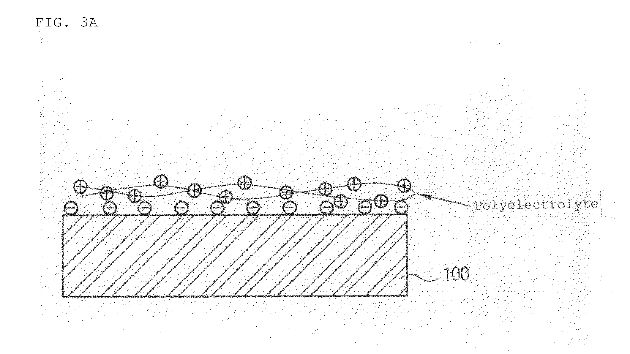
[0169]A glass supporting substrate is dipped in a piranha solution having a ratio of 3:1 of concentrated sulfuric acid (H2SO4) and 30% hydrogen peroxide (H2O2), a hydroxyl radical (OH) is formed on the surface of the glass supporting substrate and the glass substrate is cleaned with a distilled water. The processed glass supporting substrate is dipped in a solution in which the PDDA of 0.5% is melted, and is maintained in the solution for 10 minutes to 60 minutes so that a PDDA charged with a positive ion is coated on the surface of the glass supporting substrate.

[0170]In this case, a coating solution is sprayed on the surface of the glass supporting substrate or a solution is repeatedly flowed on the glass supporting substrate so that the coating solution may be sufficiently supplied to the surface of the glass supporting substrate, and the solution is stirred to have uniform concentration of the PDDA in the solution. Residual PDDA on the surface of the glass supporting substrate i...

embodiment 3

[0175]A glass supporting substrate is dipped in a piranha solution having a ratio of 3:1 of concentrated sulfuric acid (H2SO4) and 30% hydrogen peroxide (H2O2), a hydroxyl radical (OH) is formed on the surface of the glass supporting substrate and the glass substrate is cleaned with a distilled water. The processed glass supporting substrate is dipped in a solution in which the PDDA of 0.5% is melted, and is maintained in the solution for 10 minutes to 60 minutes so that a PDDA charged with a positive ion is coated on the surface of the glass supporting substrate.

[0176]In this case, a coating solution is sprayed on the surface of the glass supporting substrate or a solution is repeatedly flowed on the glass supporting substrate so that the coating solution may be sufficiently supplied to the surface of the glass supporting substrate, and the solution is stirred to have uniform concentration of the PDDA in the solution. Residual PDDA on the surface of the glass supporting substrate i...


PUM


Abstract

Disclosed are a supporting substrate for manufacturing a flexible information display device using a temporary bonding / debonding layer, a manufacturing method thereof, and a flexible information display device. A supporting substrate for manufacturing a flexible information display device, the supporting substrate comprising: a temporary bonding / debonding layer having a thickness in a range of 0.1 nm to 1000 nm and comprising an adhesive material bonded to the supporting substrate through Van der Waals bonding force. Provided is a method capable of economically manufacturing the display device having a high resolution while reviewing a cost competitive force by reducing a device investment cost and improving the yield rate in the flexible flat panel information display device.

Description

CROSS-REFERENCES TO RELATED APPLICATION[0001]This application claims priority to Korean Patent Application No. 10-2013-104534 filed on Aug. 30, 2013, the contents of which are incorporated herein by reference.BACKGROUND OF THE INVENTION[0002]1. Field of the Invention[0003]The present invention relates to a supporting substrate for manufacturing a flexible information display device using a temporary bonding / debonding layer, a manufacturing method thereof, and a flexible information display device. More particularly, the present invention relates to a supporting substrate for manufacturing a flexible information display device using a temporary bonding / debonding layer capable of easily separating the flexible information display device formed on the supporting substrate without deforming or damaging the flexible information display device when debonding the flexible information display device formed on the supporting substrate, a manufacturing method thereof, and a flexible informati...

Claims


Application Information

Patent Timeline
Patent Type & Authority Applications(United States)
IPC IPC(8): H01L27/12
CPCH01L27/1218H01L27/1229H01L27/1225H01L27/1266Y10T428/265G02F1/133305G02F1/133325
Inventor RO, JAE-SANGLEE, KEUN SOOKIM, YONG SEOKHONG, WON-EUIJANG, INGOOYANG, SEUNG-YEOLJEON, JIN NAMEKIM, KWANG JOON
Owner LEE KEUN SOO
Why Eureka
Try Eureka