Wheel drive system for an aircraft comprising a fuel cell as an energy source

a technology of fuel cell and energy source, which is applied in the direction of battery/fuel cell control arrangement, electrochemical generator, aqueous electrolyte fuel cell, etc., can solve the problem of only producing limited quantity of exhaust gases, and achieve the effect of reducing electric energy supply, and increasing electric energy supply

Inactive Publication Date: 2011-08-18
AIRBUS OPERATIONS GMBH
View PDF27 Cites 25 Cited by
  • Summary
  • Abstract
  • Description
  • Claims
  • Application Information

AI Technical Summary

Benefits of technology

[0015]It is particularly preferred to supply the electrolysis device with water from the water storage device. Consequently, the water accumulated during the normal fuel cell process could be reused and once again separated into hydrogen and oxygen while braking—during the operation of the electric motor as a generator. This could eliminate the need to withdraw water for the electrolysis device from the on-board water supply system such that it would be possible to eliminate other lines and valves. The water produced in the fuel cell could alternatively or additionally be used for cooling the conventional brakes of the landing gear, wherein the water could be sprayed onto the brakes and evaporate thereon.
[0016]A preferred wheel drive system is designed for reducing the electric energy supply to other electric consumers of the aircraft in order to increase the electric energy supply to the electric motor. If the power required for driving the landing gear is only slightly lower than the maximum power of the fuel cell, the electric energy supply to other consumers is reduced with a suitable control, wherein it would be possible, in particular, to operate the air-conditioning system for air-conditioning the aircraft cabin in the economy mode while taxing. In hot weather, the loss of comfort resulting from an air-conditioning system that runs in the economy mode can be minimized by adjusting the temperature in the aircraft cabin slightly lower than usual before taxiing such that the comfortable temperature range is not exceeded when taxiing is completed. In cold weather, the waste heat of the fuel cell may also be used for heating the cabin. The control of the consumers can be realized with the aforementioned control unit or another suitable control unit.

Problems solved by technology

A limited quantity of exhaust gases is only produced if the hydrogen is obtained from kerosene in the aircraft by means of a “reforming” process.

Method used


Image

  • Wheel drive system for an aircraft comprising a fuel cell as an energy source
  • Wheel drive system for an aircraft comprising a fuel cell as an energy source
  • Wheel drive system for an aircraft comprising a fuel cell as an energy source

Examples


Embodiment Construction

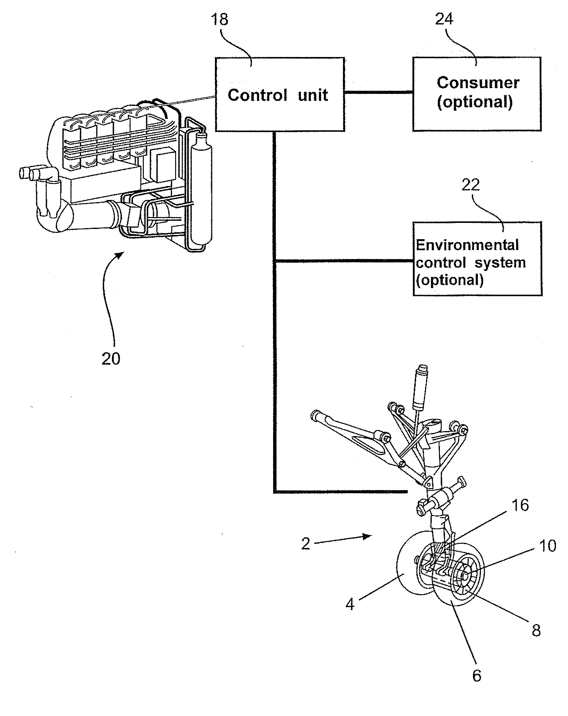
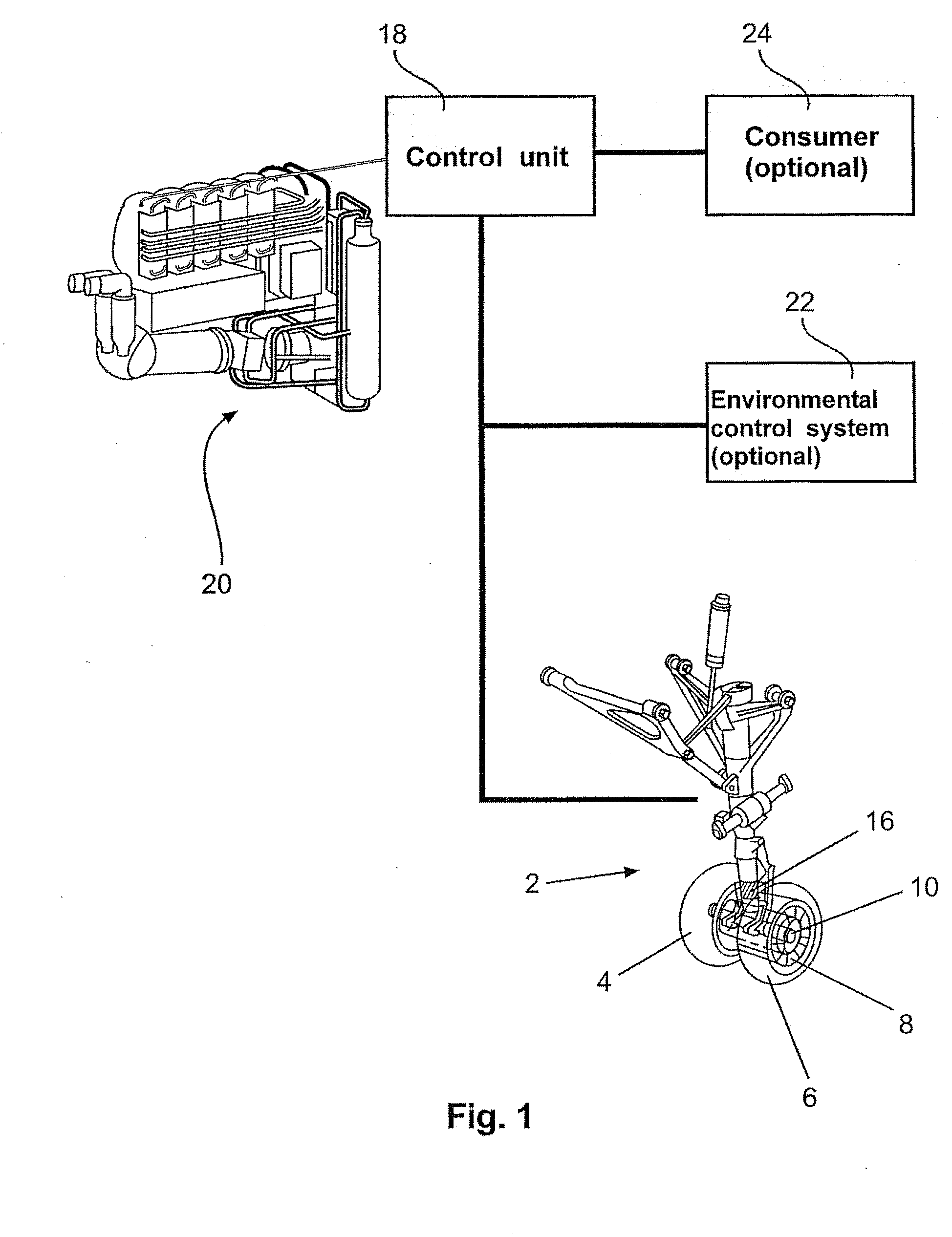
[0024]FIG. 1 shows an overview of one possible embodiment of the wheel drive system according to the invention. In addition to the usual assemblies such as wheels 4 and 6, tires, shock absorbers, latching mechanism, retracting mechanism, flaps, brakes and emergency lowering springs, the landing gear 2 also comprises the following assemblies: an electric motor 8, a gear drive 10 and control and measuring electronics / sensor 16. The electric motor 8 is coupled to the wheels 4 and 6 via a gear drive 10. A torque sensor 16 is used for determining the torque generated or absorbed by the motor 8. The determined torque value can be used, for example, for optimizing the braking process or an acceleration process and therefore the electric energy supply.

[0025]The electric motor 8 is connected to a control unit 18 that controls the supply of electric energy to the electric motor 8 and optionally to other consumers from and to a fuel cell 20. In the taxiing mode, the control unit 18 routes elec...


PUM

PropertyMeasurementUnit
torqueaaaaaaaaaa
electric energyaaaaaaaaaa
temperatureaaaaaaaaaa

Abstract

The invention pertains to a wheel drive system for an aircraft that features at least one electric motor and at least one fuel cell as energy source for the electric motor, wherein the electric motor is coupleable to at least one wheel of at least one landing gear of the aircraft. The inventive wheel drive system reduces the fuel consumption and lowers the emission of CO2 and pollutants—primarily carbon monoxide and unburned hydrocarbons. Persons, vehicles and other aircraft furthermore are not endangered by a jet blast while the aircraft is taxiing because the main engines do not have to be started until the take-off and landing strip is reached. The operation of the inventive wheel drive system furthermore leads to a reduced noise pollution.

Description

TECHNICAL FIELD[0001]The invention relates to a wheel drive system for an aircraft, the use of a wheel drive system in an aircraft, as well as an aircraft with a wheel drive system and the use of a fuel cell as energy supply for a wheel drive system in an aircraft.BACKGROUND OF THE INVENTION[0002]The taxiing of aircraft between a parking position and a take-off and landing runway is usually realized with a tow tractor and / or with the thrust of the main engines of the aircraft. The tow tractor is required, in particular, for backing the aircraft (“Push-Back”) out of its parking position (“Nose In”). The taxiing to the take-off position and from the landing point to the parking position is realized with the main engines at low thrust. In alternative procedures, the aircraft is towed to a position near the take-off position with a tow tractor such that the main engines of the aircraft can be started at the latest possible time.[0003]As an alternative, WO 2006 / 138267 A2 proposes to sele...

Claims


Application Information

Patent Timeline
Patent Type & Authority Applications(United States)
IPC IPC(8): B64C25/50H01M8/00H01M8/08
CPCB60K7/0007B60L11/1881B60L11/1892B60L11/1894Y02T90/36B64D2041/005Y02T50/823Y02T90/34B64C25/405B60L58/30B60L58/33B60L58/34Y02T50/80Y02T90/40
Inventor ROTGER, THOMASHEINRICH, HANS-JURGENKURRE, JENS-DIETRICH
Owner AIRBUS OPERATIONS GMBH
Why Eureka
Try Eureka