Wireless power feeding system and wireless power feeding method

a power feeding system and wireless technology, applied in the direction of safety/protection circuits, inductances, transportation and packaging, etc., can solve the problems of difficulty in specifying or managing power, and achieve the effect of convenient power feeding for users and high power transmission efficiency

Inactive Publication Date: 2012-02-02
SEMICON ENERGY LAB CO LTD
View PDF2 Cites 24 Cited by
  • Summary
  • Abstract
  • Description
  • Claims
  • Application Information

AI Technical Summary

Benefits of technology

[0040]In power feeding performed by the power feeding device and the power receiver, a power signal is transmitted to the power receiver at an optimum frequency for high power transmission efficiency on the basis of the position and resonant frequency information of the power receiver; accordingly, power can be supplied to the power receiver without waste.
[0041]Therefore, it is possible to provide a power feeding system and a power feeding method which are more convenient for a power feeding user.
[0042]It is possible to provide a power feeding system and a power feeding method which also allow a power feeding provider (a company) which feeds power (at the power transmitting end) to supply power to a power receiver without waste.
[0043]It is possible to provide a power feeding system and a power feeding method which can offer a power feeding service efficient to both a user and a provider by specifying and managing a power feeding user at the power receiving end and properly controlling the amount of power supplied to a power receiver.

Problems solved by technology

However, a contactless power feeding system has a problem in that it has difficulty specifying or managing a power feeding user who receives power (at the power receiving end), controlling the amount of power supplied to a power receiver, and the like because it is a contactless system.

Method used


Image

  • Wireless power feeding system and wireless power feeding method
  • Wireless power feeding system and wireless power feeding method
  • Wireless power feeding system and wireless power feeding method

Examples


embodiment 1

[0056]In this embodiment, an embodiment of a wireless power feeding system and a wireless power feeding method is described with reference to FIGS. 1 to 4.

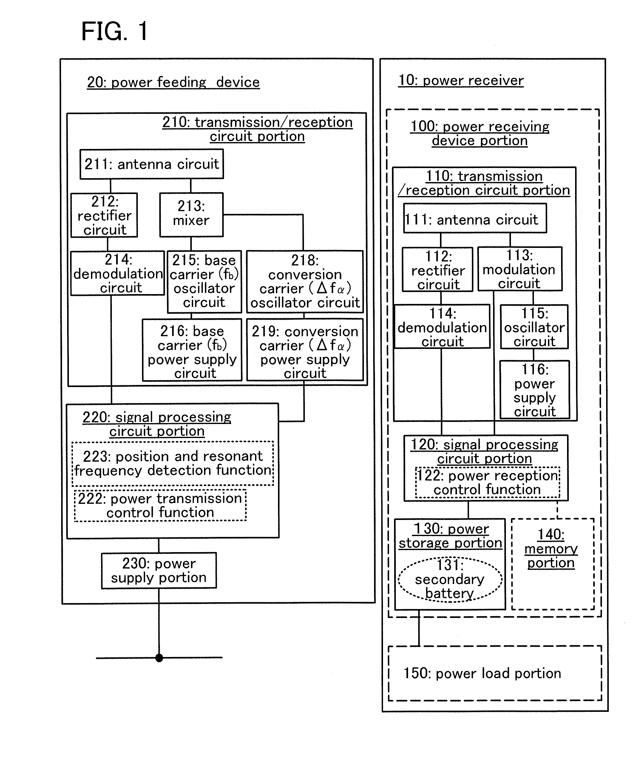
[0057]FIG. 1 illustrates components of a power feeding device and a power receiver included in the wireless power feeding system of this embodiment, in independent blocks which are classified according to their functions. However, there is not necessarily a one-to-one correspondence between components and functions, and the power feeding system may operate using a plurality of components and a plurality of functions in conjunction with each other.

[0058]In the wireless power feeding system in FIG. 1, a power feeding device 20 and a power receiver 10 transmit and receive signals to and from each other wirelessly (by an electromagnetic wave), and power is supplied from the power feeding device 20 to the power receiver 10 without contact.

[0059]The power feeding device 20 includes a transmission / reception circuit portion 210 which tran...

embodiment 2

[0103]In this embodiment, another embodiment of a wireless power feeding system and a wireless power feeding method is described with reference to FIG. 5 and FIG. 6.

[0104]FIG. 6 illustrates components of a power feeding device and a power receiver included in the wireless power feeding system of this embodiment, in independent blocks which are classified according to their functions. FIG. 6 illustrates an example where a detection portion (a voltage / current detection portion 160) which detects the amount of power stored in the secondary battery 131 of the power storage portion 130 is provided in the wireless power feeding system in FIG. 1 described in Embodiment 1. The same portions as or portions having functions similar to those in Embodiment 1 are similar to those in Embodiment 1 and repetitive description will be omitted. In addition, detailed description of the same portions is not repeated.

[0105]The voltage / current detection portion 160 detects the voltage, the current, or the...

embodiment 3

[0121]In this embodiment, another embodiment of a wireless power feeding system and a wireless power feeding method is described with reference to FIG. 7 and FIGS. 8A and 8B.

[0122]In this embodiment, an example is described in which a step of recognizing identification information of the power receiver is added before the position and resonant frequency detection step in Embodiment 1 or 2. The same portions as or portions having functions similar to those in Embodiment 1 or 2 are similar to those in Embodiment 1 or 2 and repetitive description will be omitted. In addition, detailed description of the same portions is not repeated.

[0123]Identification information can be stored in the memory portion of the power receiver. In addition, the signal processing circuit portion of the power feeding device has an identification function to identify the identification information.

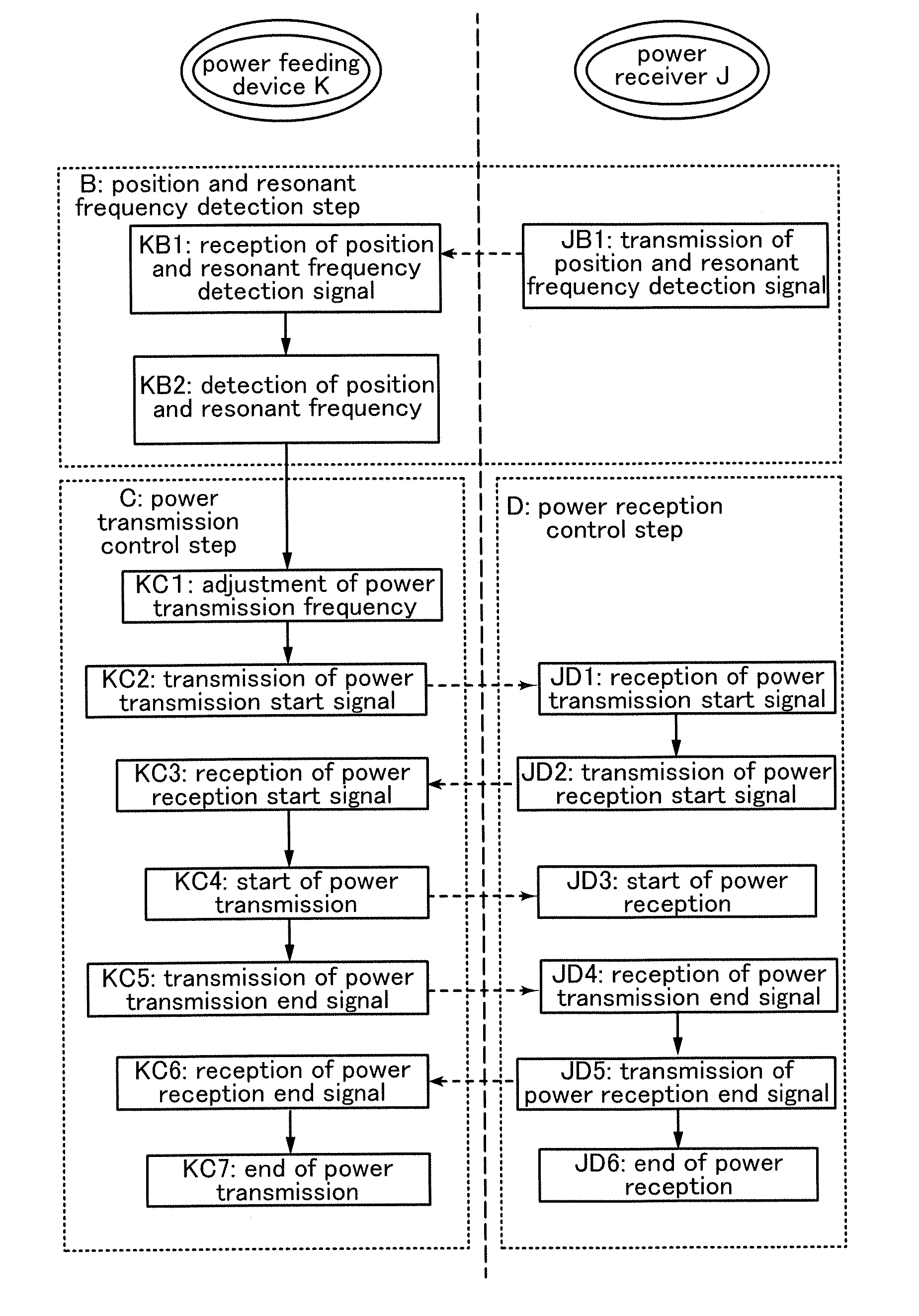
[0124]A wireless power feeding method of this embodiment is described with reference to a flow chart of FIG. 7. No...


PUM

PropertyMeasurementUnit
frequencyaaaaaaaaaa
frequencyaaaaaaaaaa
frequencyaaaaaaaaaa

Abstract

A power feeding device which wirelessly supplies power to a power receiver receives a position and resonant frequency detection signal from the power receiver, detects the position and the resonant frequency of the power receiver, and controls the frequency of a power signal to be transmitted to the power receiver on the basis of the information. As the power signal for power transmission, two signals having different frequencies, which are generated using a mixer by mixing a base carrier (a first signal) with a conversion carrier (a second signal) generated on the basis of the resonant frequency, are used.

Description

BACKGROUND OF THE INVENTION[0001]1. Field of the Invention[0002]The present invention relates to a wireless power feeding system and a wireless power feeding method.[0003]2. Description of the Related Art[0004]In recent years, electronic devices using electric power as driving power, as typified by mobile devices such as mobile phones or notebook personal computers, are often used while being carried.[0005]In addition, transportation means such as bicycles and automobiles which use electric power as driving power have been developed in terms of its cleanness and safety in the aspect of environment.[0006]It is difficult to supply power to such electronic devices and transportation means, which are used outside the house or while in motion, constantly from a commercial power supply distributed to each house, through wires. Therefore, portable electronic devices and transportation means incorporate batteries which are charged from a commercial power supply in advance and operate by bei...

Claims


Application Information

Patent Timeline
Patent Type & Authority Applications(United States)
IPC IPC(8): H01F38/14H02J4/00H02J7/00
CPCH04B5/0037H02J5/005H02J50/90H02J7/00302H02J50/12H02J50/40H04B5/0075H02J7/00
Inventor KAMATA, KOICHIROSATO, MISAKOMAEDA, SHUHEI
Owner SEMICON ENERGY LAB CO LTD
Why Eureka
Try Eureka