Power feeding device, wireless power feeding system using the same and wireless power feeding method

a technology of wireless power feeding and power feeding method, which is applied in the direction of safety/protection circuit, battery overcharge protection, inductance, etc., can solve problems such as difficult specification or management, and achieve the effect of simplifying the structure of the power receiver, high transmission efficiency and high transmission efficiency

Active Publication Date: 2012-03-15
SEMICON ENERGY LAB CO LTD
View PDF3 Cites 25 Cited by
  • Summary
  • Abstract
  • Description
  • Claims
  • Application Information

AI Technical Summary

Benefits of technology

[0051]In power feeding performed by the power feeding device and the power receiver, the power feeding device transmits a power signal to the power receiver at an optimum frequency with high transmission efficiency; accordingly, power can be supplied to the power receiver without waste. Also, specification of the optimum frequency with high transmission efficiency is performed in the power feeding device by determining a reflection coefficient. Therefore, it is not necessary to transmit information for specifying the optimum frequency from the power receiver to the power feeding device, and a structure of the power receiver can be simplified.
[0052]Accordingly, a power feeding device, a power feeding system, and a power feeding method which are more convenient for a power feeding user at the power receiving end can be provided.
[0053]A power feeding device, a power feeding system, and a power feeding method which allows a power feeding provider (a company) on the power feeding side (power transmitting side) to supply power without waste, can be provided.
[0054]A power feeding device, a power feeding system, and a power feeding method by which an efficient power feeding service is possible for both the user and the provider, by specifying and managing the power feeding user on the power receiving end and properly controlling the amount of power supplied to a power receiver, can be provided.

Problems solved by technology

However, because contactless power feeding devices and power feeding systems operate without contact, there are problems in that they have difficulty specifying or managing a power feeding user who is to receive power (at the power receiving end), controlling the amount of power that is supplied to a power receiver, and the like.

Method used


Image

  • Power feeding device, wireless power feeding system using the same and wireless power feeding method
  • Power feeding device, wireless power feeding system using the same and wireless power feeding method
  • Power feeding device, wireless power feeding system using the same and wireless power feeding method

Examples


embodiment 1

[0068]In this embodiment, an embodiment of a wireless power feeding system and a wireless power feeding method is described with reference to FIGS. 1 to 4, and FIG. 11.

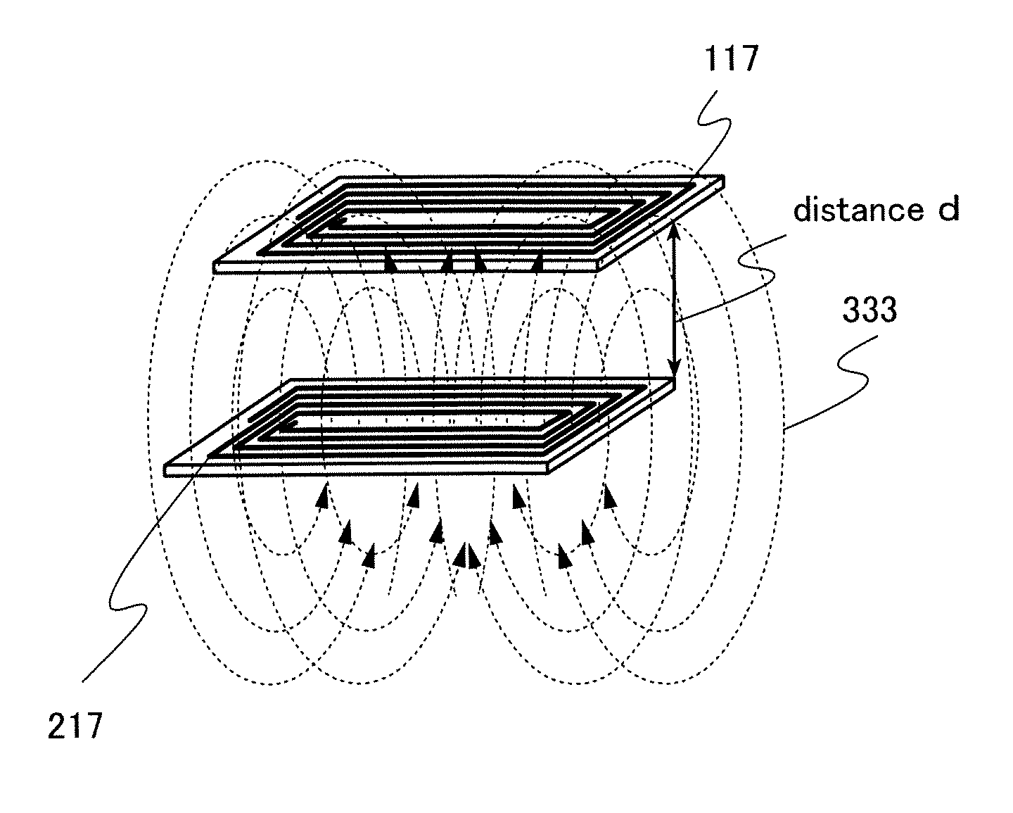
[0069]Note that in this specification, a distance between a power feeding device and a power receiver is the shortest distance between an antenna provided in the power feeding device and an antenna of the power receiver. FIG. 4 illustrates an example of power feeding with a distance d between a power receiver antenna 117 included in a power receiver and a power feeding device antenna 217 included in a power feeding device. In FIG. 4, the power receiver antenna 117 and the power feeding device antenna 217 are positioned with a distance d therebetween, and power feeding is performed by generating a magnetic field 333. FIG. 4 illustrates an example of power feeding by an electromagnetic induction method using coil antennas as antennas, and illustrates an embodiment of an antenna shape and a transmission method of an elec...

embodiment 2

[0126]In this embodiment, another embodiment of a wireless feeding system and a wireless power feeding method is described with reference to FIG. 5 and FIG. 6.

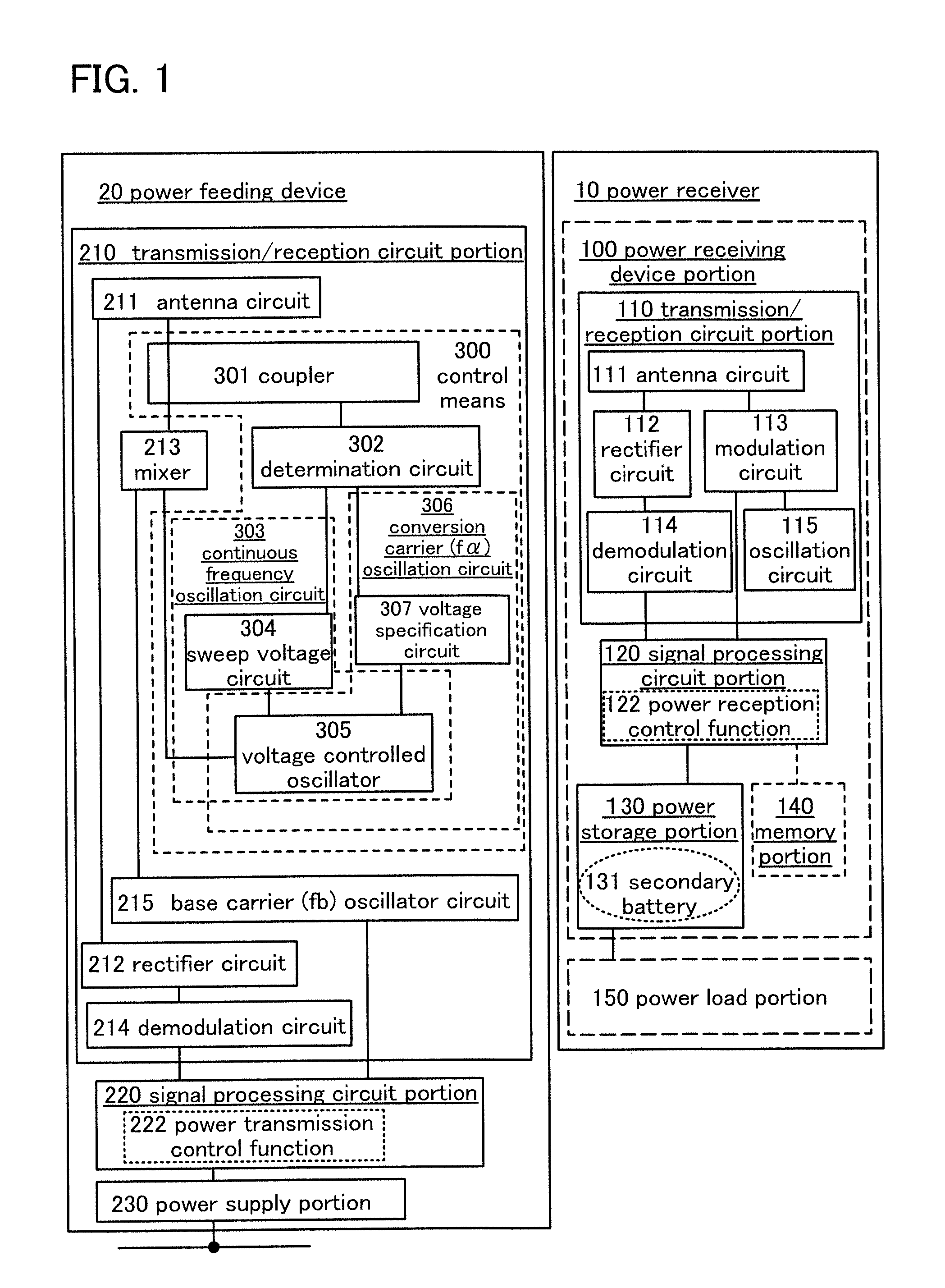
[0127]FIG. 6 illustrates components of a power feeding device and a power receiver included in the wireless power feeding system of this embodiment, in separate blocks according to function. FIG. 6 illustrates an example where a detection portion (a voltage / current detection portion 160) which detects the amount of power stored in the secondary battery 131 of the power storage portion 130 is provided in the wireless power feeding system in FIG. 1 described in Embodiment 1, and the same portions as or portions having functions similar to those in Embodiment 1 are similar to those in Embodiment 1 and repetitive description will be omitted. In addition, detailed description of the same portions is not repeated.

[0128]The voltage / current detection portion 160 detects a voltage, a current, or a voltage and a current of the secondary...

embodiment 3

[0135]In this embodiment, another embodiment of a wireless power feeding system and a wireless power feeding method is described with reference to FIG. 7 and FIGS. 8A and 8B. FIG. 1 and FIG. 10 are also referred to for the description.

[0136]In this embodiment, an example is described in which a step of recognizing identification information of the power receiver is added to Embodiment 1 or Embodiment 2. The same portions as or portions having functions similar to those in Embodiment 1 are similar to those in Embodiment 1 or 2 and repetitive description will be omitted. Furthermore, detailed description of the same portions is omitted.

[0137]Identification information can be stored in the memory portion 140 of the power receiver. Also, the signal processing circuit portion 220 of the power feeding device has an identification function for identifying the identification information.

[0138]A wireless power feeding method of this embodiment is illustrated in a flow chart of FIG. 7. Note t...


PUM


Abstract

An object is to provide a power feeding device, a power feeding system, and a power feeding method which are more convenient for a power feeding user at the power receiving end. The power feeding device includes a means of controlling a frequency of a power signal transmitted to a power receiver, based on a proportion of signals, among power signals output to an antenna circuit, that return from the power receiver to the antenna circuit without feeding power to the power receiver.

Description

BACKGROUND OF THE INVENTION[0001]1. Field of the Invention[0002]The present invention relates to a power feeding device, a wireless power feeding system, and a wireless power feeding method.[0003]2. Description of the Related Art[0004]In recent years, electronic devices using electric power as a driving power, which are typified by mobile devices such as mobile phones or laptop personal computers, are often used while being carried.[0005]Also, transportation means such as bicycles and automobiles using electric power as a driving power have been developed from the point of view of environmental cleanness and safety.[0006]It is difficult to constantly supply power to electronic devices and transportation means that are used outdoors or while traveling, by a wire from a commercial power supply distributed to each house. Therefore, mobile electronic devices and transportation means are provided with batteries that are charged from a commercial power supply in advance, and are operated ...

Claims


Application Information

Patent Timeline
Patent Type & Authority Applications(United States)
IPC IPC(8): H02J17/00
CPCH02J17/00H02J5/005H02J50/20H02J50/80H02J50/40H02J50/10H02J7/00302H04B1/44H02J50/90H02J50/05H02J50/12
Inventor KAMATA, KOICHIROSATO, MISAKOMAEDA, SHUHEI
Owner SEMICON ENERGY LAB CO LTD
Why Eureka
Try Eureka