Monitoring apparatus and monitoring object apparatus

a technology of monitoring object and monitoring apparatus, which is applied in the direction of mechanical roughness/irregularity measurement, testing/monitoring control system, instruments, etc., can solve the problems of increased maintenance cost and safety hazards of operators, and achieve the effect of increasing maintenance cost and normal operating ratio

Inactive Publication Date: 2005-02-10
ARKRAY INC
View PDF11 Cites 28 Cited by
  • Summary
  • Abstract
  • Description
  • Claims
  • Application Information

AI Technical Summary

Benefits of technology

[0005] With the foregoing in mind, it is an object of the present invention to provide a monitoring system that allows a maintenance check to be performed at an appropriate time with respect to a monitored device by monitoring the state of the device through a communication network so as to detect an indication of an abnormality, thereby allowing the device to achieve a higher normal operating ratio and the suppression of an increase in maintenance cost.

Problems solved by technology

Particularly, the occurrence of a failure in a device may hinder an operator of the device from performing a smooth operation or also may cause safety hazards to the operator.
However, in the case where the time for a check / replacement is set based simply on a past experience rule or life data for each component or the like as described above, since there are life variations even among components of the same type due to the differences in usage conditions and the like, the following problem may arise.
That is, contrary to expectations, a failure may be caused before the time for a check / replacement, or conversely, a component that still has sufficient life may have to be replaced, thereby resulting adversely in an increase in the maintenance cost, which has been disadvantageous.

Method used


Image

  • Monitoring apparatus and monitoring object apparatus
  • Monitoring apparatus and monitoring object apparatus
  • Monitoring apparatus and monitoring object apparatus

Examples


embodiment 1

[0040] (Embodiment 1) Hereinafter, the present invention will be described by way of an embodiment with reference to the appended drawings.

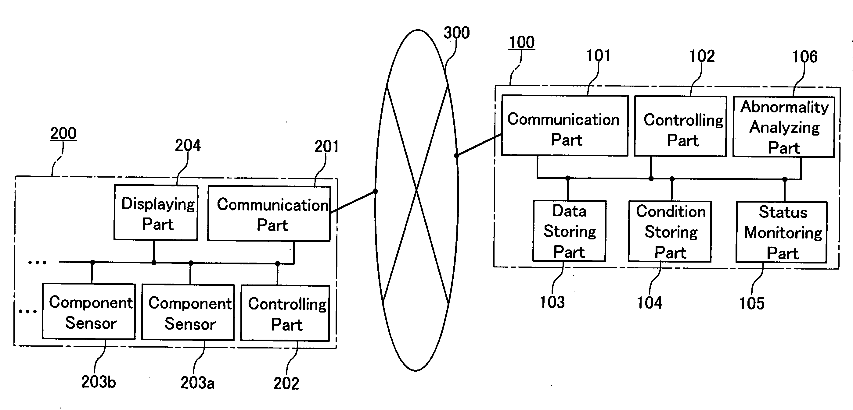
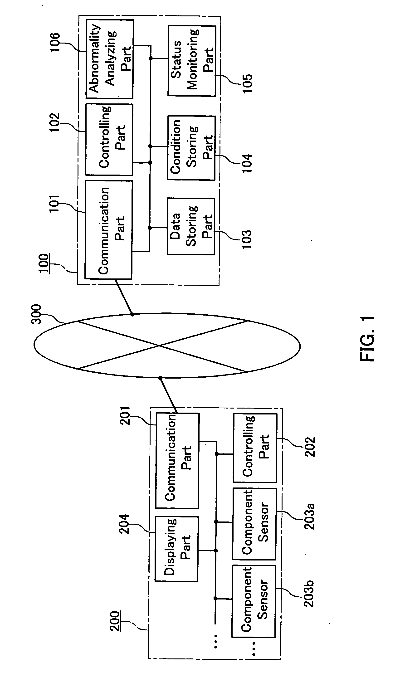
[0041] As shown in FIG. 1, a monitoring system according to this embodiment has a configuration in which a host computer 100 (monitoring device) of a manufacturer / dealer of a device such as a clinical testing device or the like and a clinical testing device 200 (monitored device) that has been delivered to a user by this manufacturer / dealer are connected to each other through a communication network 300 such as the Internet. In FIG. 1, for the sake of simplicity, only one unit of the clinical testing device 200 is shown. However, an arbitrary number of units of the clinical testing devices 200 are connected to the host computer 100.

[0042] The communication network 300 is not limited to the Internet mentioned above and can be formed of any communication medium that is capable of bi-directional communication. Through this communication network 300...

embodiment 2

[0069] (Embodiment 2)

[0070] Hereinafter, the present invention will be described by way of another embodiment.

[0071] In this embodiment, as an example of the clinical testing device 200, a device is used that is provided with a test strip feeder part (not shown in FIG. 1) supplying a testing part with test strips. The description is directed to a mechanism in which an operational abnormality of this device is predicted by the host computer 100.

[0072] As shown in FIG. 4, a test strip feeder included in the clinical testing device 200 is a mechanism for sequentially supplying a predetermined testing part with test strips one at a time. A test strip is a thin and short strip having one side with a surface on which many different types of reagent pads are disposed.

[0073] As shown in FIG. 4, the test strip feeder includes a base 1, supports 2, supporting members 3a and 3b, a rotor 4, a lodging portion 5, a test strip detecting block 6, an inclined cover 7, a drum 8, a base member 9, a...


PUM


Abstract

A monitoring system for monitoring the state of a monitoring object apparatus so as to detect a foretoken of failure. A host computer (100) of a manufacturer/dealer of a clinical check apparatus (200) receives state data of respective parts from parts sensors (203a, 203b, . . . ) of the clinical check apparatus (200) of a user and the received state data is compared to a prediction condition stored in a condition storage block (104) in a state monitoring block (105), thereby detecting a foretoken of failure. The prediction condition includes a condition created in accordance with service life of each of the parts and a condition created upon occurrence of a failure in accordance with transition of the state data prior to the occurrence of the failure.

Description

TECHNICAL FIELD [0001] The present invention relates to a system in which a monitoring device remotely monitors various devices to be monitored through a communication network so as to predict a failure or the like of each of the monitored devices. BACKGROUND ART [0002] Generally, with respect to various testing devices including clinical testing devices, machine tools or automobiles, or various types of other devices requiring precise operations, manufacturers / dealers of such devices, after delivery of the devices, continuously perform maintenance so that performance of the devices is maintained and safety is secured. Particularly, the occurrence of a failure in a device may hinder an operator of the device from performing a smooth operation or also may cause safety hazards to the operator. Therefore, with a view to improving customer satisfaction, suppressing an increase in maintenance cost and securing safety, it has been of great importance to perform a periodic check of a devic...

Claims


Application Information

Patent Timeline
Patent Type & Authority Applications(United States)
IPC IPC(8): G01D3/08G01D21/00G05B23/02
CPCG01D3/08G05B23/0264G05B23/0227G01D21/00
Inventor WADA, ATSUSHIHARADA, TOSHIHIKO
Owner ARKRAY INC
Why Eureka
Try Eureka