
METHODS AND APPARATUS OF FUSING RADAR/CAMERA OBJECT DATA AND LiDAR SCAN POINTS

a technology of radar/camera object data and fusing method, applied in the direction of distance measurement, instruments, surveying and navigation, etc., can solve the problem of limited to a single consequence and significant consequences for application softwar

Active Publication Date: 2013-09-19
GM GLOBAL TECH OPERATIONS LLC
View PDF6 Cites 107 Cited by
  • Summary
  • Abstract
  • Description
  • Claims
  • Application Information

AI Technical Summary

Benefits of technology

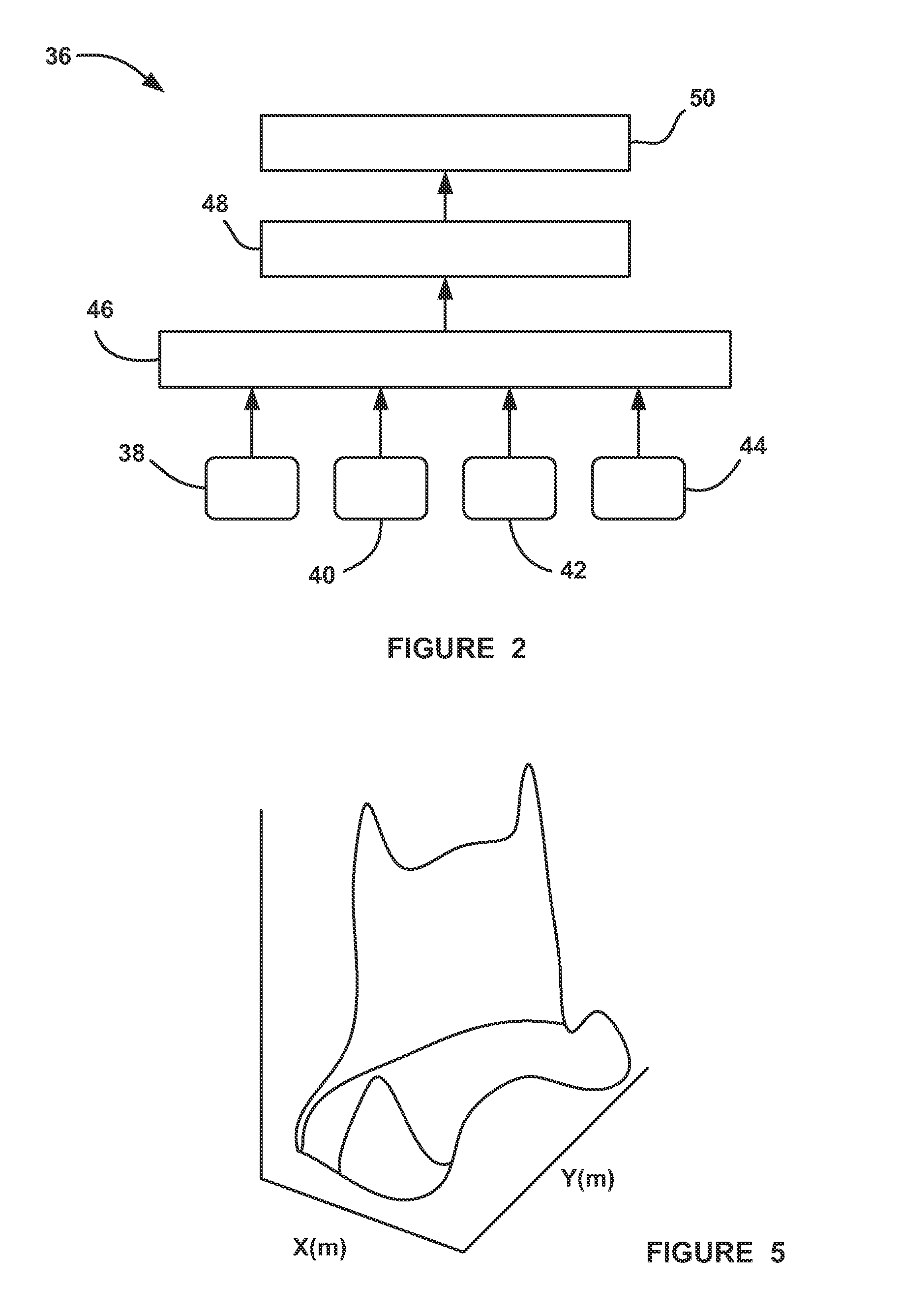
The present invention is a system and method for fusing the output of multiple LiDAR sensors on a vehicle. The system detects objects through radar and vision systems and creates object models that identify the position, orientation, and velocity of the detected objects. The system then projects these object models to predict the future trajectory of the objects. The system then receives scan returns from the sensors and matches the predicted object models with the detected targets. The system merges predicted object models that were previously separate scan clusters and splits other predicted object models based on the match with the target data. The system also creates new object models and deletes dying object models based on the match with the target data. The system provides object model updates that include the merger of object models, split models, new models, and deletion of models. This invention improves the accuracy and efficiency of object detection and recognition on vehicles.

Problems solved by technology

For example, if a sensor detects an object that is actually in the path of the host vehicle but, due to sensor misalignment, the sensor determines that the object is slightly to the left of the path of the host vehicle, this can have significant consequences for the application software.
This application is limited to a single LiDAR sensor, and does not discuss fusing returns from multiple LiDAR sensors.

Method used


Image

  • METHODS AND APPARATUS OF FUSING RADAR/CAMERA OBJECT DATA AND LiDAR SCAN POINTS
  • METHODS AND APPARATUS OF FUSING RADAR/CAMERA OBJECT DATA AND LiDAR SCAN POINTS
  • METHODS AND APPARATUS OF FUSING RADAR/CAMERA OBJECT DATA AND LiDAR SCAN POINTS

Examples


Embodiment Construction

[0036]The following discussion of the embodiments of the invention directed to a system and method fusing the outputs from multiple LiDAR sensors on a vehicle, where the fusion process is cued by an object detected by a radar sensor or a vision system is merely exemplary in nature, and is in no way intended to limit the invention or its applications or uses. For example, the present invention will be described for fusing the outputs of LiDAR sensors on a vehicle. However, as will be appreciated by those skilled in the art, the fusing process of the invention will have application other than vehicle applications.

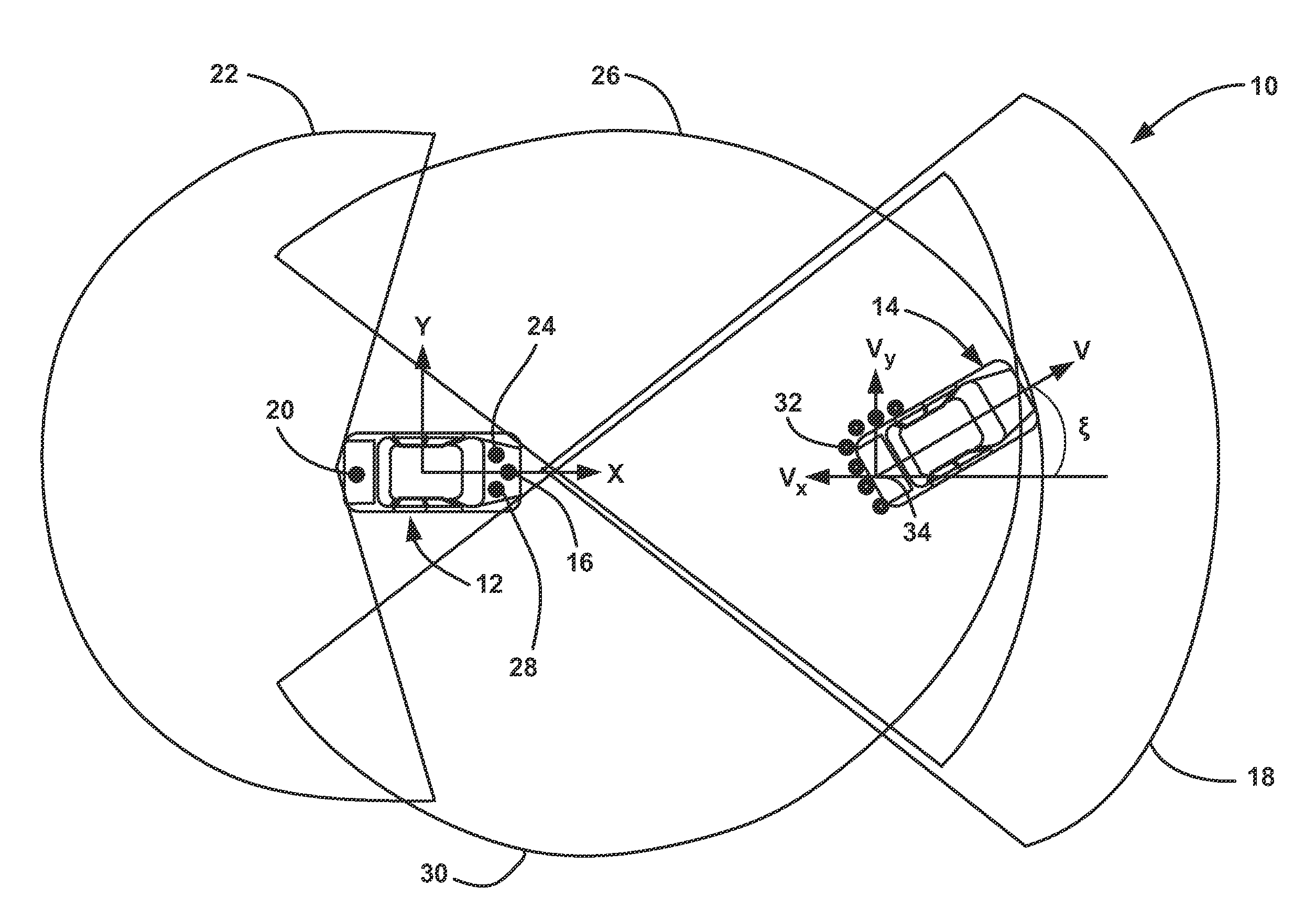
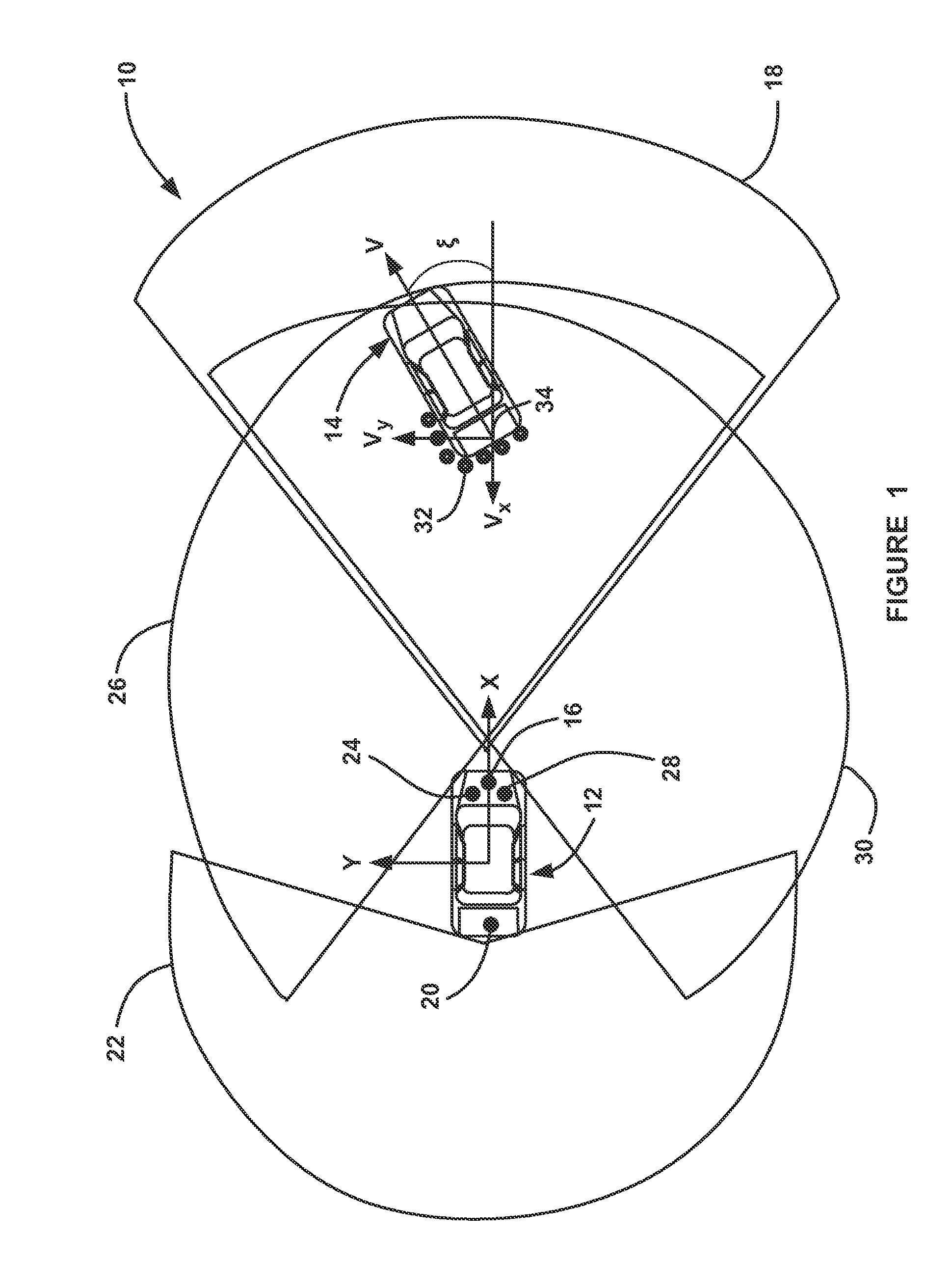
[0037]FIG. 1 illustrates an overview of a vehicle system 10 including a host vehicle 12 shown trailing a target vehicle 14 that it is tracking. The host vehicle 12 includes four LiDAR sensors, namely, a forward looking sensor 16 having a field-of-view 18, a rearward looking sensor 20 having a field-of-view 22, a left looking sensor 24 having a field-of-view 26 and a right loo...


PUM


Abstract

A system and method for fusing the outputs from multiple LiDAR sensors on a vehicle that includes cueing the fusion process in response to an object being detected by a radar sensor and / or a vision system. The method includes providing object files for objects detected by the LiDAR sensors at a previous sample time, where the object files identify the position, orientation and velocity of the detected objects. The method projects object models in the object files from the previous sample time to provide predicted object models. The method also includes receiving a plurality of scan returns from objects detected in the field-of-view of the sensors at a current sample time and constructing a point cloud from the scan returns. The method then segments the scan points in the point cloud into predicted scan clusters, where each cluster identifies an object detected by the sensors.

Description

CROSS-REFERENCE TO RELATED APPLICATIONS[0001]This application claims the benefit of the priority date of U.S. Provisional Patent Application Ser. No. 61 / 611,492, titled, Methods and Apparatus of Fusing Radar / Camera Object Data and LiDAR Scan Points, filed Mar. 15, 2012.BACKGROUND OF THE INVENTION[0002]1. Field of the Invention[0003]This invention relates generally to a system and method for fusing the outputs from multiple sensors on a vehicle and, more particularly, to a system and method for fusing scan points from multiple LiDAR sensors on a vehicle, where the process for fusing the LiDAR sensor scan points is cued in response to an object being detected by a radar sensor or a vision system on the vehicle.[0004]2. Discussion of the Related Art[0005]Many modern vehicles include object detection sensors that are used to enable collision warning or avoidance and other active safety applications. The object detection sensors may use any of a number of detection technologies, such as ...

Claims


Application Information

Patent Timeline
Patent Type & Authority Applications(United States)
IPC IPC(8): G01S17/66G01S17/87G01S17/86G01S17/931
CPCG01S17/66G01S17/936G01S17/87G01S17/931G01S17/86
Inventor ZENG, SHUQING
Owner GM GLOBAL TECH OPERATIONS LLC
Learn More