Direct current converter and control circuit and method for the direct current converter

A DC converter and control circuit technology, applied in the direction of converting DC power input to DC power output, control/regulation systems, instruments, etc., can solve the influence of slope compensation signal switch duty cycle, the peak value change of inductor current, and the maximum output current. restrictions, etc.

Active Publication Date: 2011-02-02
CHENGDU MONOLITHIC POWER SYST
View PDF4 Cites 33 Cited by
  • Summary
  • Abstract
  • Description
  • Claims
  • Application Information

AI Technical Summary

Problems solved by technology

[0006] The purpose of the present invention is to solve the problem that the current peak value of the inductor current changes and the maximum output current is limit

Method used


Image

  • Direct current converter and control circuit and method for the direct current converter
  • Direct current converter and control circuit and method for the direct current converter
  • Direct current converter and control circuit and method for the direct current converter

Examples


Embodiment Construction

[0029] Specific embodiments of the present invention will be described in detail below. It should be noted that the embodiments described here are for illustration only, and are not intended to limit the present invention.

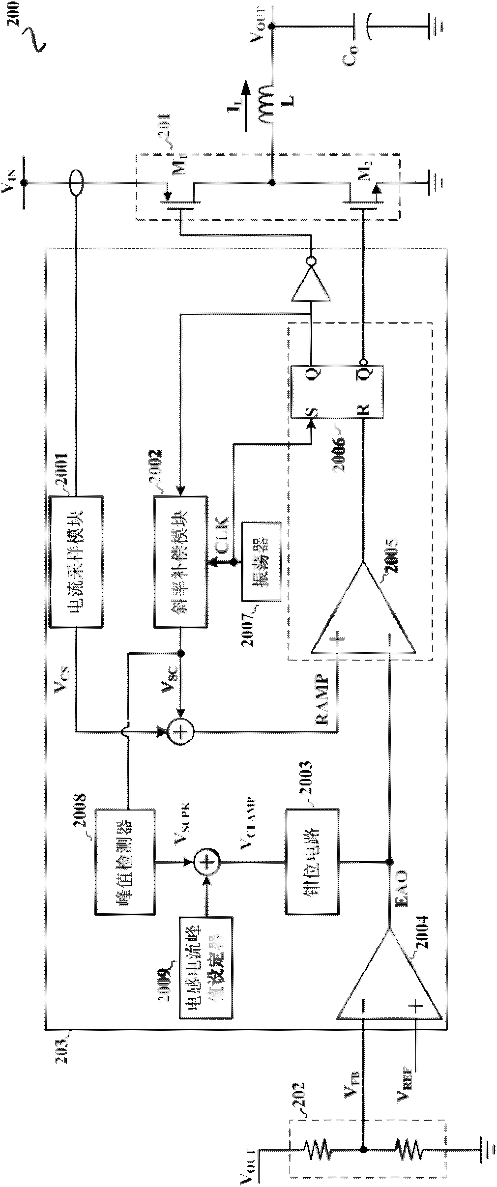
[0030] refer to image 3 , is a DC converter 200 according to an embodiment of the present invention. Such as image 3 As shown, the DC converter 200 includes an output stage 201 coupled between the input terminal of the DC converter 200 and the ground; the inductor L and the output capacitor C O The composed LC filter is coupled to the output stage 201; the feedback circuit 202 is used for output voltage V of the DC converter 200 OUT , providing the feedback signal V FB ; and the control circuit 203, coupled to the feedback circuit 202 and the output stage 201, to receive the feedback signal V FB , reference signal V REF and the inductor current signal I L , providing a control signal to the output stage 201 . In one embodiment, the output stage c...


PUM


Abstract

The invention discloses a control circuit for a direct current converter, comprising a current sampling module for providing a current sample signal based on an inductive current of the direct current converter; a slope compensation module for providing the slope compensation signal based on a clock signal and a control signal; a peak detector for detecting the amplitude value of the slope compensation signal and providing the peak detection signal; an error amplifier for providing the error amplifying signal based on a feedback signal and a reference signal; a clipper for clipping the error amplification signal based on the peak detection signal and the inductive current setting peak value; a compared logic module for providing the control signal to control the output level of the directcurrent converter based on the clock signal, the error amplifying signal, the slope compensation signal and the current sampling signal. The invention also comprises a method corresponding with the circuit. The real induction current peak value is adjusted to the required induction current peak value by adjusting the inductive current based on the inductive current limit signal RAMP and the clipping signal VCLAMP, therefore the output current of the direct current converter is limited.

Description

technical field [0001] The present invention relates to direct current to direct current (DC) converters, and more particularly, the present invention relates to peak current mode controlled DC converters. Background technique [0002] Peak current mode control is widely used in DC converters. Peak current mode control usually adopts slope compensation technology, so that the system can still achieve stable operation when the duty cycle of the DC converter exceeds 50%. The slope compensation technique superimposes a slope compensation signal and an inductor current sampling signal to set the inductor current limit. State-of-the-art peak current mode controlled DC converters such as figure 1 shown. [0003] figure 1 The DC converter 100 is controlled for a prior art peak current mode. Such as figure 1 As shown, the DC converter 100 includes an upper transistor M 1 and down tube M 2 The output stage 101 composed of an inductor L and an output capacitor C O LC filter c...

Claims


Application Information

Patent Timeline
IPC IPC(8): H02M3/158
CPCH02M3/156
Inventor 席小玉周坚
Owner CHENGDU MONOLITHIC POWER SYST
Why Eureka
Try Eureka