Solar charging booster circuit

A booster circuit, solar energy technology, applied in battery circuit devices, charging/maintenance charging/discharging, circuit devices, etc., can solve problems such as low collection voltage, avoid battery damage, wide market application prospects, and accurate and fast response adjustment. Effect

Inactive Publication Date: 2017-10-20
CHENGDU ANGDIJIA TECH CO LTD
View PDF6 Cites 0 Cited by
  • Summary
  • Abstract
  • Description
  • Claims
  • Application Information

AI Technical Summary

Problems solved by technology

At present, solar panels have the problem of low collection voltage, so it is difficult to directly transmit electric energy to the battery through solar panels, and increasing the transmission voltage can improve the charging efficiency of the battery to a certain extent, so how to effectively carry out solar energy Charging is a burning problem

Method used


Image

  • Solar charging booster circuit

Examples


Embodiment

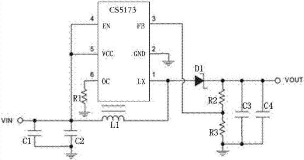
[0012] Such as figure 1 As shown, the solar charging boost circuit includes a boost chip CS5173 with 6 legs, a resistor R1 connected to pin 6 of the boost chip and grounded, and connected in parallel with pins 4 and 5 of the boost chip Capacitor C1 and Capacitor C2, both connected to the pins, are connected to the inductance L1 of the boost chip's 1st and 4th pins respectively, connected to the booster chip's 1st pin and connected to the diode D1 at the output of the circuit, connected to the booster chip The resistor R2 between pin 3 and the output terminal of the circuit, one end connected to pin 3 of the boost chip and the other end grounded resistor R3, and the capacitor C3 and capacitor C4 connected in parallel with one end connected to the circuit output terminal and the other end grounded. , The input end of the circuit is connected to pin 4 of the boost chip, and pin 2 of the boost chip is grounded.

[0013] Preferably, the diode D1 is a Schottky diode.


PUM


Abstract

The invention discloses a solar charging booster circuit which comprises the components of a booster chip CS5173 with six pins, a resistor R1 which is connected with a sixth pin of the booster chip and is grounded, a capacitor C1 and a capacitor C2 which are connected in parallel and are connected with a fourth pin and a fifth pin of the booster chip, an inductor L1 of which the two ends are respectively connected with a first pin and a fourth pin of the booster chip, a diode D1 which is connected with the first pin of the booster chip and the output end of the circuit, a resistor R2 which is connected between a third pin of the booster chip and the output end of the circuit, a resistor R3 of which one end is connected with the third pin of the booster chip and the other end is grounded, and a capacitor C3 and a capacitor C4 which are connected in parallel, wherein one end of an assembly which is composed of the parallelly connected capacitor C3 and the capacitor C4 is connected with the output end of the circuit, and the other end is grounded. According to the solar charging booster circuit, the CS5173 booster chip and a Schottky diode are utilized for realizing a stable voltage output. Furthermore the solar charging booster circuit has advantages of effectively suppressing output current, preventing high temperature of the circuit caused by overhigh current, effectively isolating a solar cell panel from a storage battery, and preventing battery damage caused by direct charging.

Description

Technical field [0001] The invention relates to a solar battery auxiliary circuit, in particular to a solar charging boost circuit. Background technique [0002] With the development and progress of science and technology, the energy on the earth is gradually decreasing, and mankind has begun to pay attention to solar energy, an inexhaustible energy source. Solar panels are an important component for humans to harvest solar energy. However, because solar energy is not always available for harvesting, when using solar panels for solar energy harvesting, it is often necessary to store the energy in a battery before outputting it for use, especially if there is no Use solar energy in the sun's rays. At present, solar panels have the problem of low collection voltage. Therefore, it is difficult to directly transmit electric energy to the storage battery through solar panels. However, increasing the transmission voltage can improve the charging efficiency of the battery to a certain ...

Claims


Application Information

Patent Timeline
Patent Type & Authority Applications(China)
IPC IPC(8): H02J7/35H02J7/00
CPCH02J7/0029H02J7/00304H02J7/0069H02J7/35H02J2207/20Y02E10/56
Inventor 周建英
Owner CHENGDU ANGDIJIA TECH CO LTD
Why Eureka
Try Eureka