Work vehicle equipped with rear monitoring camera apparatus

a technology for working vehicles and cameras, applied in soil-shifting machines/dredgers, roofs, transportation and packaging, etc., can solve problems such as damage to rear monitoring cameras and drawbacks, and achieve the effect of reliably inhibiting the elevation of temperature of rear monitoring cameras

Active Publication Date: 2012-06-14
KOMATSU LTD
View PDF4 Cites 13 Cited by
  • Summary
  • Abstract
  • Description
  • Claims
  • Application Information

AI Technical Summary

Benefits of technology

[0009]The present invention has been produced in view of the aforementioned drawbacks. It is an object of the present invention to provide a work vehicle equipped with a rear monitoring camera apparatus having less chances of damage by external obstacles without blocking a rear field of view.
[0011]According to the work vehicle of the first aspect of the present invention, at least the main body of the rear monitoring camera is accommodated within the blower part cover. Therefore, the rear monitoring camera does not block a rear view compared to the structure that the entire rear monitoring camera is downwardly protruded from the blower part cover. Further, it is possible for the rear monitoring camera to have less chances of damage by external obstacles compared to the structure that the entire rear monitoring camera is protruded from the rear part of the blower cover.
[0014]According to the work vehicle of the third aspect of the present invention, the rear monitoring camera is disposed between the cooling fans. Therefore, the rear monitoring camera does not block the flow of the blown wind from the cooling fans. Further, the blown wind, heated as a result of heat exchange with the condenser, does not directly hit the rear monitoring camera. Consequently, it is possible to inhibit reduction in the flow amount of the blown wind and elevation in temperature of the rear monitoring camera.
[0016]According to the work vehicle of the fourth aspect of the present invention, it is possible to further inhibit reduction in the flow amount of the blown wind from the cooling fans.
[0018]According to the work vehicle of the fifth aspect of the present invention, the anti-vibration rubber can inhibit not only vibration transmission from the cab to the rear monitoring camera but also thermal transmission from the wind shielding cover warmed due to the impact of the blown wind from the cooling fans to the rear monitoring camera. Further, an air layer is formed in a clearance between the wind shielding cover and the rear monitoring camera by the anti-vibration rubber interposed therebetween. Therefore, it is possible to more reliably inhibit elevation in temperature of the rear monitoring camera.
[0019]Overall, according to the present invention, it is possible to provide a work vehicle equipped with a rear monitoring camera apparatus disposed and structured to be less damaged by external obstacles without blocking a rear field of view.

Problems solved by technology

However, a drawback is produced when the rear monitoring camera is disposed on the bottom face of the rear part of the air conditioner, because the rear monitoring camera itself blocks a field of view of an operator in the cab when the operator looks back through a rear window.
A drawback is also produced when the rear monitoring camera is disposed on the rear face of the rear part of the air conditioner, because the rear monitoring camera may be damaged by the contact with external obstacles.

Method used


Image

  • Work vehicle equipped with rear monitoring camera apparatus
  • Work vehicle equipped with rear monitoring camera apparatus
  • Work vehicle equipped with rear monitoring camera apparatus

Examples


Embodiment Construction

[0026]Next, a work vehicle including a support structure for a rear monitoring camera apparatus according to an embodiment of the present invention will be hereinafter specifically explained with reference to the attached drawings. It should be noted that the present invention is applied to a bulldozer as a work vehicle in the following example. However, applications of the present invention are not limited to the bulldozer.

Explanation of Schematic Structure of Bulldozer

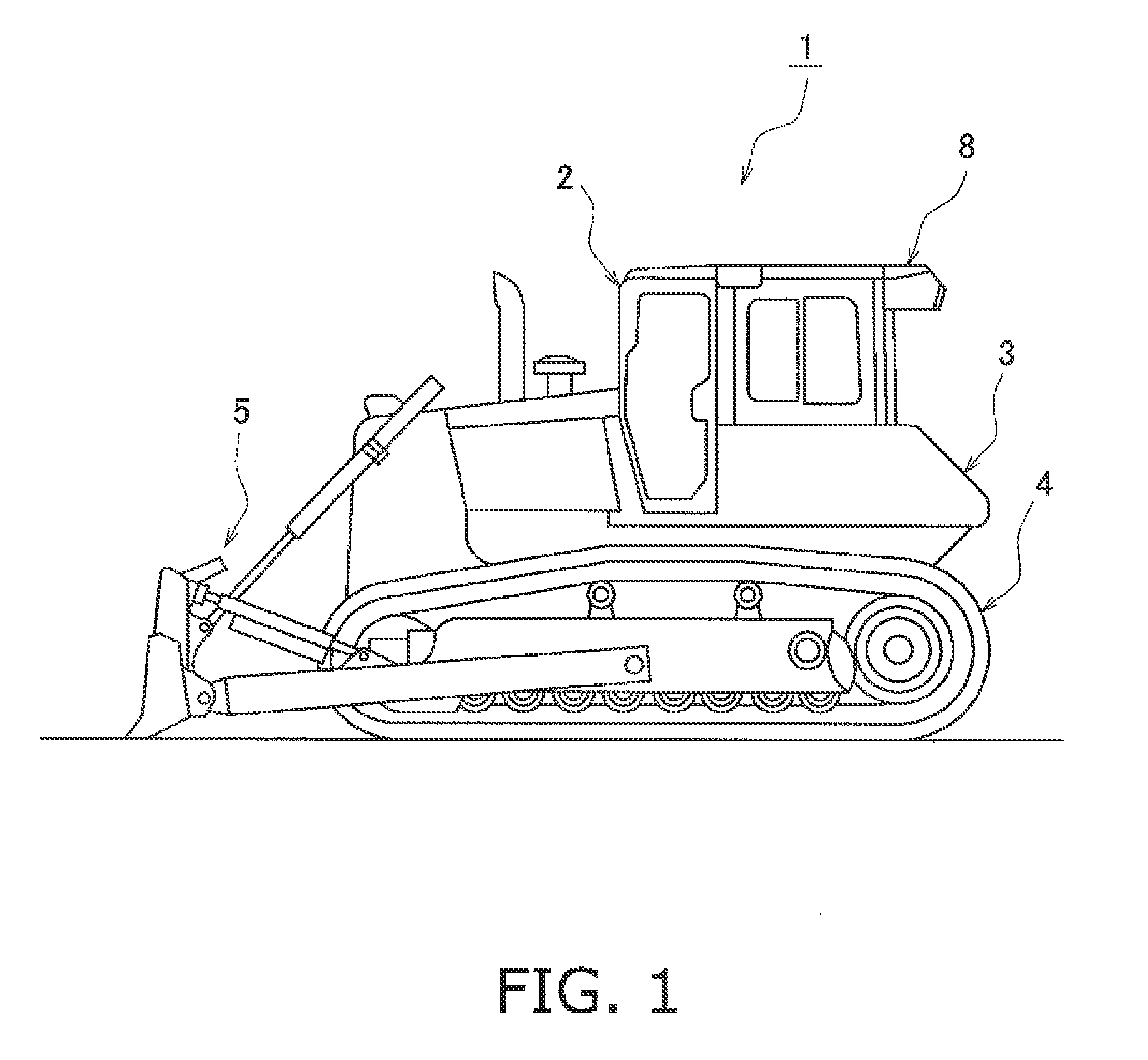
[0027]A bulldozer 1 illustrated in FIG. 1 includes a vehicle body 3 which is embedded with a cab 2 forming an operator's room, a drive unit 4 which is a track-type drive unit including a pair of tracks (only a left-side track is illustrated in the figure) disposed on the both lateral sides of the vehicle body 3, and a front work implement (blade device) 5 which is disposed on the front side of the vehicle body 3.

Explanation of Air Conditioner

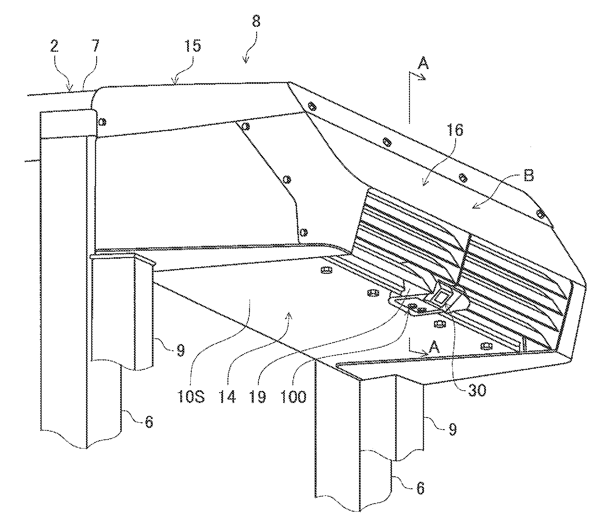
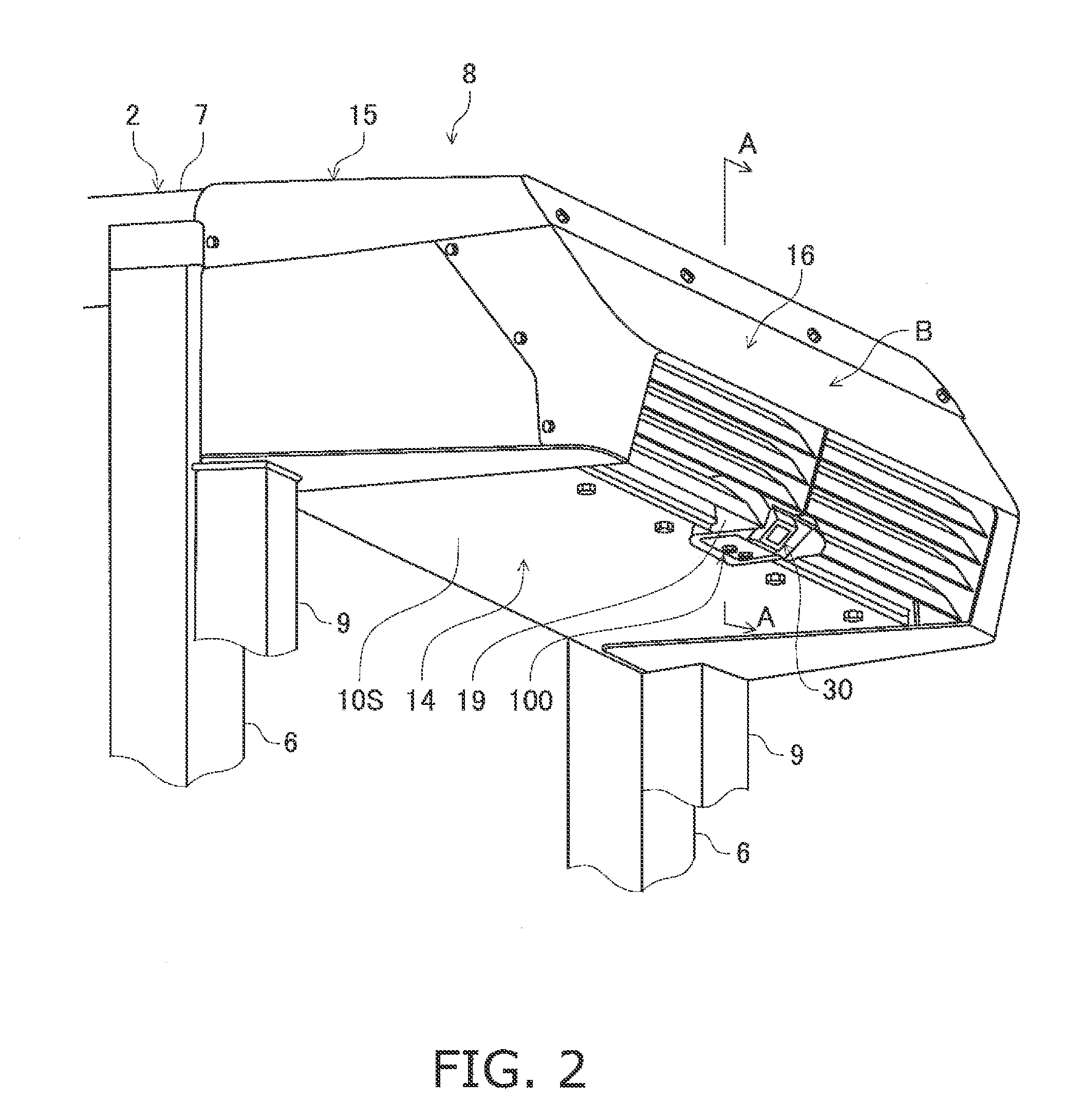
[0028]As illustrated in FIG. 2, an air conditioning device 8 is attached to ...


PUM


Abstract

A work vehicle includes a cab, an air conditioner casing, an air conditioner unit and a rear monitoring camera. The air conditioner casing is attached to a rear upper part of the cab and includes a downwardly opened recess on a bottom face thereof. The air conditioner unit is accommodated in the air conditioner casing. The rear monitoring camera includes a main body accommodated in the recess of the air conditioner casing.

Description

CROSS-REFERENCE TO RELATED APPLICATIONS[0001]This application claims priority to Japanese Patent Application No, 2010-180082 filed on Aug. 11, 2010, the disclosure of which is hereby incorporated herein by reference in its entiretyBACKGROUND OF THE INVENTION[0002]1. Field of the Invention[0003]The present invention relates to a work vehicle equipped with a rear monitoring camera apparatus for monitoring the back thereof.[0004]2. Background Art[0005]Some of the well-known work vehicles of the type (e.g., bullozers) include an air conditioning device (hereinafter simply referred to as “an air conditioner”) attached to the rear part of a cab (for example, see Japanese Patent Application Laid-Open 2009-096222A).[0006]The aforementioned work vehicles are assumed to be equipped with a rear monitoring camera for monitoring the back thereof, and the rear monitoring camera can be disposed on the bottom or rear face of the rear part of the air conditioner.[0007]However, a drawback is produced...

Claims


Application Information

Patent Timeline
Patent Type & Authority Applications(United States)
IPC IPC(8): B60H1/32H04N7/18
CPCE02F9/0858E02F9/26E02F9/163E02F9/261
Inventor NAGAMI, KOUJIYOMOGITA, MAKOTOMIYAZAKI, MASAMICHIMATSUMOTO, JUN
Owner KOMATSU LTD
Why Eureka
Try Eureka