Wire connection device

a wire connection and wire technology, applied in the direction of connection contact material, coupling device connection, electrical apparatus, etc., can solve the problem of shortening the service life of the wire connection device, and achieve the effect of reducing the chance of damage to the wire connection devi

Active Publication Date: 2022-06-28
HEAVY POWER
View PDF2 Cites 2 Cited by
  • Summary
  • Abstract
  • Description
  • Claims
  • Application Information

AI Technical Summary

Benefits of technology

[0017]This invention is characterized by the fact that the lever is equipped with an actuating cam, which allows the lever to swing to the actuate position relative to the housing, and the actuating cam may also change the position of the area in contact with the conductor so that the lever may be moved in a straight line relative to the housing at the same time. In addition, the conductor has the push-back block and the lever has the push-back notch for the lever to be in the actuate position. The lever not only squeezes into the wire clamping portion, but the push-back block penetrates into the push-back notch, allowing the lever to hold in the actuate position. In this way, when the wire clamping portion of the conductor is deformed by squeezing of the lever, the lever remains in the actuate position so that the leaf spring remains in the deformed state. This allows the wire to be penetrated into the wire connection device without squeezing the leaf spring so that both the leaf spring and the conductive member can be clamped to the wire, which relatively reduces the chance of damage to the wire connection device.

Problems solved by technology

However, when the conductor is deformed by the wire extrusion, the conductor generates an elastic force on the wire, and when the wire penetrates into the inside of the housing through the insertion hole, the wire is easily misaligned in the conductor due to the elastic force and thus cannot be clamped by the conductor; thereby, the wire must be repeatedly inserted into the inside of the housing so that the structure pattern of the conductor will generate the elastic force due to repeated plugging and unplugging, resulting in the conductor becoming elastically fatigued and unable to clamp the conductor to the wire, therefore, the conductor becoming unusable and relatively shortening the service life of the wire connection device.
Otherwise, once the user releases his or her hand, the conductor will move the lever back to the initial position through the elastic force, resulting in inconvenience when the wire is inserted inside the housing.

Method used


Image

  • Wire connection device
  • Wire connection device
  • Wire connection device

Examples


Embodiment Construction

[0033]Hereinafter, preferred embodiments of the present invention are cited, and further detailed description is given as follows in conjunction with the drawings.

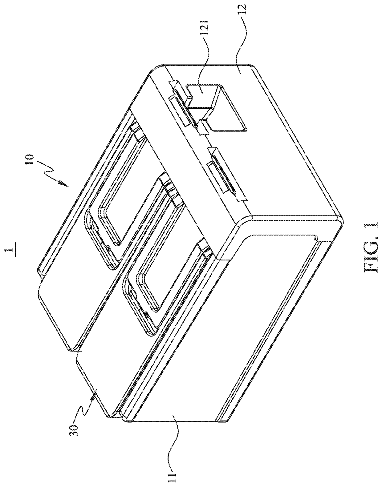
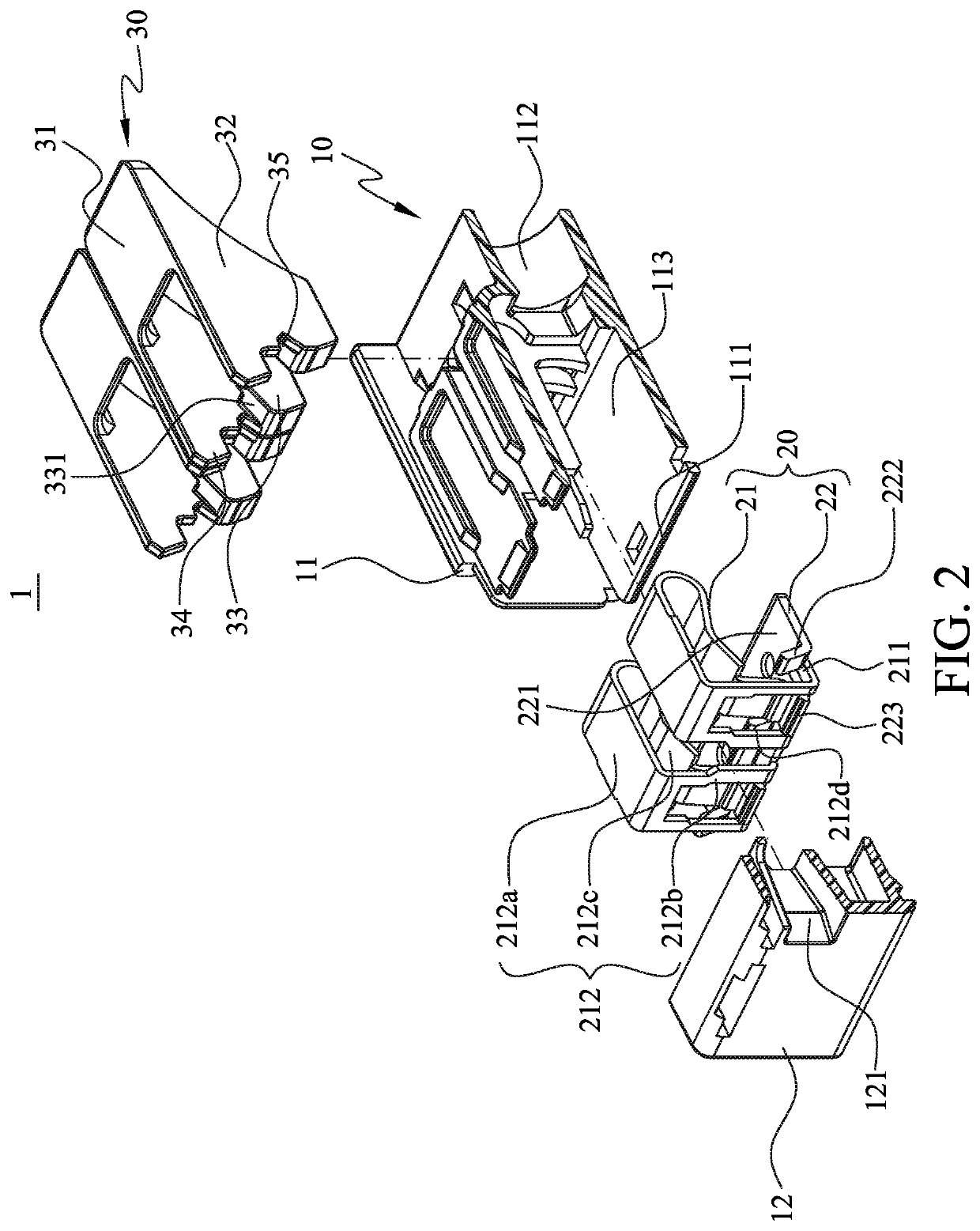
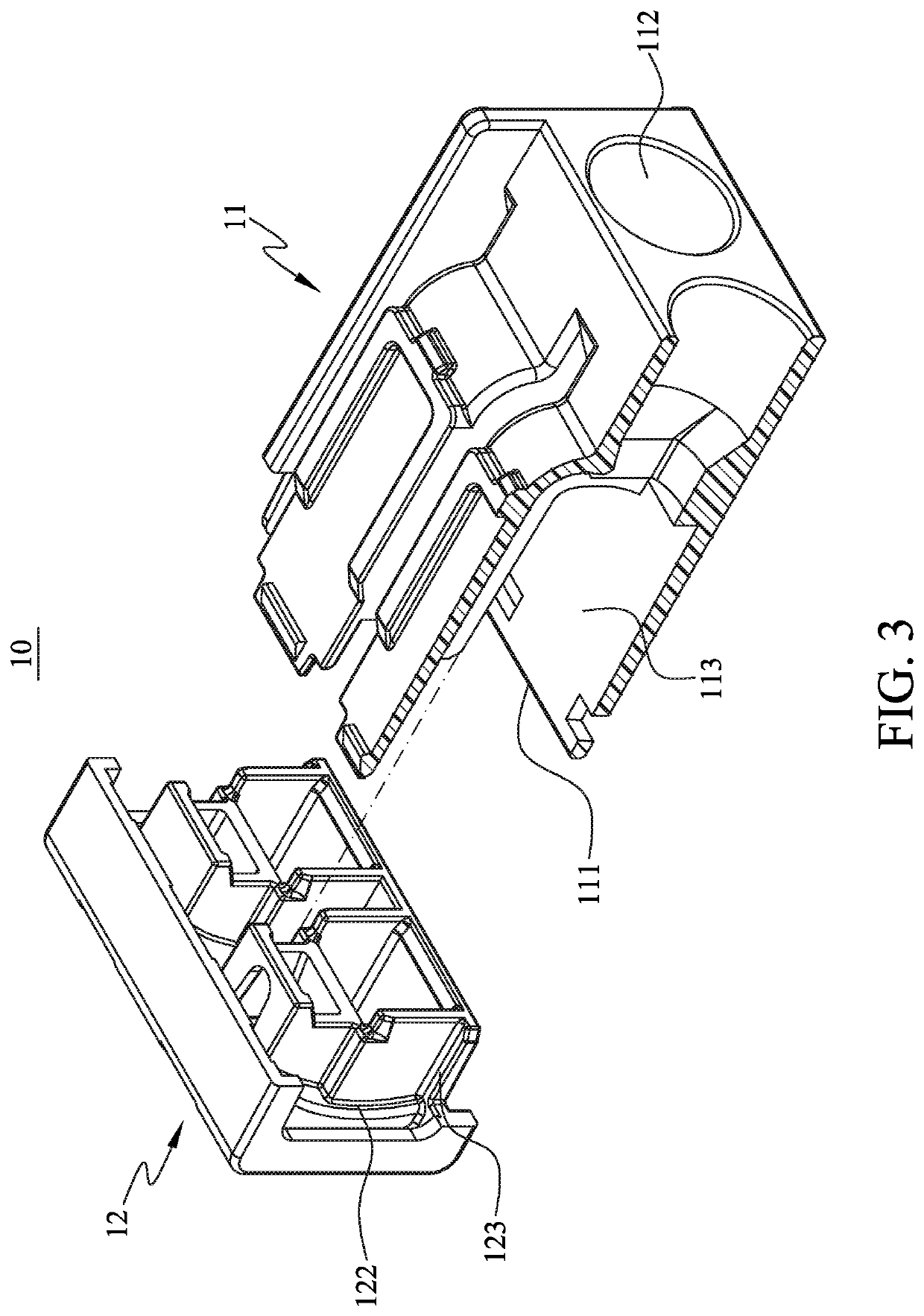
[0034]With reference to FIGS. 1 to 3, in a first preferred embodiment, a wire connection device 1 of the present invention consists mainly of a housing 10, a conductor 20 and two levers 30. With reference to FIGS. 2 and 3, the housing 10 has a hollow housing 11 in a hollow configuration and a cover 12 attached to the hollow housing 11. As shown in the figure, the hollow housing 11 is provided with a mounting hole 111 on one side near the cover 12, and the hollow housing 11 is provided with two insertion holes 112 of different shapes from the mounting hole 111 on one side away from the mounting hole 111. Furthermore, the hollow housing 11 is internally formed with an accommodation space 113 between the mounting hole 111 and the insertion hole 112 so that the mounting hole 111 is communicated to each of the insertion holes 1...


PUM


Abstract

A wire connection device includes a housing, a conductor, and a lever. The conductor is located inside the housing and has a leaf spring, a conductive member and a push-back block, and the lever is provided with a push-back notch and an actuating cam, and the lever is movably assembled in the housing so that the lever may swing against the housing so that the leaf spring is squeezed by the lever for generating a deformation. When the lever swings to an actuate position, the touch surface of the cam that touch the conductor will be changed so that the lever can be moved in a straight line against the housing simultaneously. Therefore, the push-back block can be inserted into the inside of the push-back notch. In this way, when the push-back block is positioned inside the push-back notch, the lever is kept stay so that the leaf spring is kept in a state of deformation by the lever, and the wire can insert into the wire connection device without push the leaf spring, so that the wire connection device won't be damaged easily.

Description

FIELD OF THE INVENTION[0001]The present invention relates to a wire connection device for electrically connecting an electric product to an external power source, and in particular to a wire connection device that prevents damage when a wire is inserted.BACKGROUND OF THE INVENTION[0002]In general, a wire connection device is used to electrically connect an electric product to an external power source so that the electric product can be temporarily or permanently electrically connected to the external power source through the electrical connection device.[0003]The basic structure of a common wire connection device today is formed with a housing and a conductor. The housing is hollow and has an insertion hole communicated to the inside of the housing; the conductor is positioned inside the housing and is on one side of the insertion hole. In this way, when a wire is inserted into the interior of the housing through the insertion hole, the wire is pressed against the conductor so that ...

Claims


Application Information

Patent Timeline
Patent Type & Authority Patents(United States)
IPC IPC(8): H01R4/64H01R4/48H01R9/24
CPCH01R4/4827H01R4/64H01R9/2416H01R31/08H01R4/48455H01R4/48365H01R4/48275
Inventor TSENG, CHIEG-LI
Owner HEAVY POWER
Why Eureka
Try Eureka