Battery assembly

a battery and assembly technology, applied in the field of batteries, can solve the problems of high potential of damage to batteries and inconvenience of operation, and achieve the effects of reducing the chance of damage to batteries, and extending the service li

Active Publication Date: 2022-02-03
DARFON ELECTRONICS CORP
View PDF6 Cites 2 Cited by
  • Summary
  • Abstract
  • Description
  • Claims
  • Application Information

AI Technical Summary

Benefits of technology

[0017]Compared with the prior art, the battery assembly of the invention has a two-stage engaging mechanism between the battery unit and the battery holding unit, not only to enhance the holding effect between the battery unit and the battery holding unit, but also to provide the user sufficient time to release the second-stage engagement of the battery unit and the battery holding unit after the first-stage engagement is released. Consequently, the battery assembly of the invention can effectively prevent the battery unit from directly falling off to reduce the chance of damaging the battery unit and to improve the operation convenience. Moreover, the battery assembly of the invention can reduce the space for the engaging mechanism between the battery unit and the battery holding unit by disposing the engaging portion rotatable along the end surface.

Problems solved by technology

However, when the battery is to be replaced or removed, users generally have to hold the battery by one hand and release the locking mechanism by the other hand.
Consequently, when the locking mechanism is unlocked by one hand, and the other hand cannot immediately support the battery, the battery will directly fall off the bicycle frame, resulting in high potential of damaging the battery and inconvenience of operation.

Method used


Image

  • Battery assembly
  • Battery assembly
  • Battery assembly

Examples


Embodiment Construction

[0033]The invention provides a battery assembly, which can be applied to an electric bicycle, but not limited thereto. The battery assembly of the invention can be applied to any suitable device, which requires a two-stage engaging mechanism, to provide safe and convenient operations of the battery assembly. Hereinafter, the structure and operation of elements of the battery assembly of the invention will be described in detail with reference to the drawings.

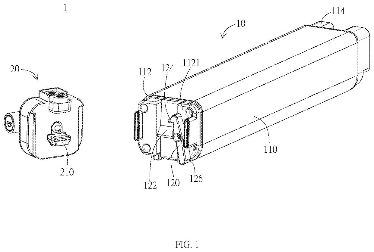
[0034]FIG. 1 is a schematic view of the battery assembly in an embodiment of the invention. As shown in FIG. 1, the battery assembly 1 includes a battery unit 10 and a battery holding unit 20. The battery unit 10 is removably held by the battery holding unit 20. The battery unit 10 includes a battery 110, a first engaging portion 122, and a second engaging portion 124. The first engaging portion 122 and the second engaging portion 124 are disposed on an end portion 112 of the battery 110, and the second engaging portion 124 is r...


PUM

PropertyMeasurementUnit
angleaaaaaaaaaa
angleaaaaaaaaaa
external forceaaaaaaaaaa

Abstract

A battery assembly includes a battery holding unit and a battery unit removably held by the battery holding unit. The battery unit includes a battery, a first engaging portion and a second engaging portion disposed on an end portion of the battery. The battery holding unit includes a holding member selectively engaging with the first engaging portion or the second engaging portion to hold the battery unit at a first position or a second position. When the holding member and the first engaging portion relatively move away from each other, the battery unit moves from the first position to the second position at which the holding member engages with the second engaging portion, and the second engaging portion is allowed to rotate along a surface of the end portion to disengage from the holding member and to remove the battery unit from the battery holding unit.

Description

BACKGROUND OF THE INVENTION1. Field of the Invention[0001]The invention generally relates to a battery assembly. Particularly, the invention relates to a battery assembly with a two-stage engaging mechanism.2. Description of the Prior Art[0002]Electric bicycles generally utilize batteries as the power source for motors, and the battery is usually mounted on the bicycle frame. In order to prevent the battery from falling off the bicycle frame, locking mechanism is generally provided to secure the battery. However, when the battery is to be replaced or removed, users generally have to hold the battery by one hand and release the locking mechanism by the other hand. Consequently, when the locking mechanism is unlocked by one hand, and the other hand cannot immediately support the battery, the battery will directly fall off the bicycle frame, resulting in high potential of damaging the battery and inconvenience of operation.SUMMARY OF THE INVENTION[0003]It is an object of the invention ...

Claims


Application Information

Patent Timeline
Patent Type & Authority Applications(United States)
IPC IPC(8): H01M50/244H01M50/264
CPCH01M50/244H01M50/264Y02E60/10H01M50/249H01M50/262B62J43/13H01M2220/20B62J43/23B62M6/90B62H5/001
Inventor LIU, CHIH-HSIEN
Owner DARFON ELECTRONICS CORP
Why Eureka
Try Eureka