Removing electrophotographic carrier particles from photoreceptor

a carrier particle and photoreceptor technology, applied in the field of electrophotographic printing, can solve the problems of physical damage to the photoreceptor and image artifacts, and achieve the effects of reducing the chance of damage to the latent image, and reducing the probability of cleaning off the carrier

Inactive Publication Date: 2012-05-17
EASTMAN KODAK CO
View PDF2 Cites 2 Cited by
  • Summary
  • Abstract
  • Description
  • Claims
  • Application Information

AI Technical Summary

Benefits of technology

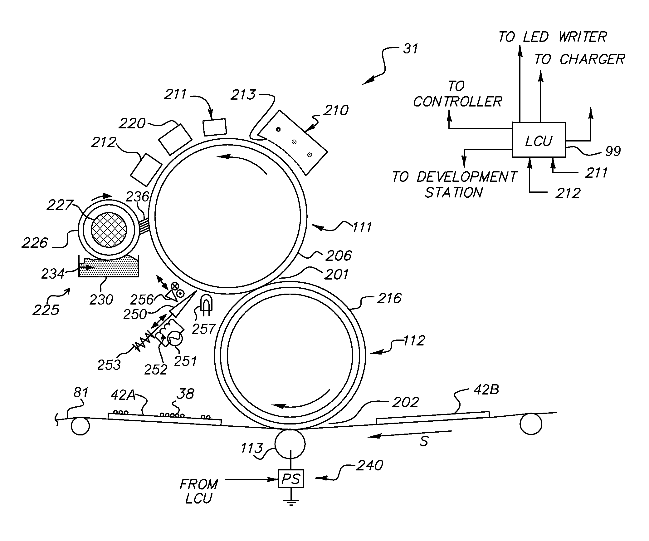
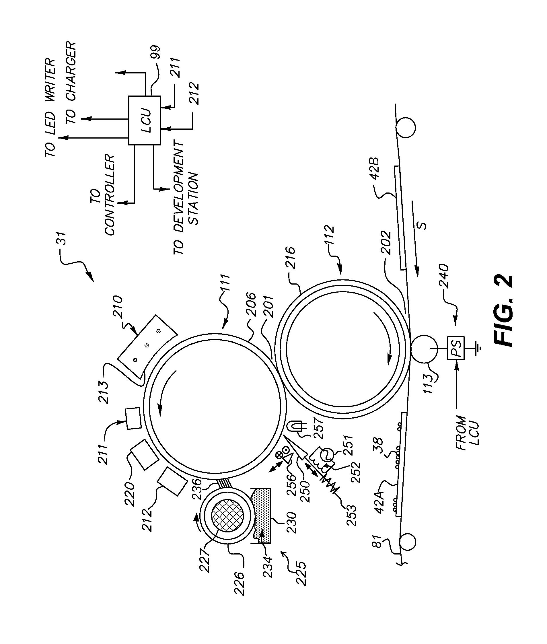
[0016]An advantage of this invention is that it uses mechanical forces to help remove carrier particles in addition to using electrical or magnetic forces. Various embodiments remove carrier particles with reduced risk of those particles' scratching the photoreceptor. Strong electrostatic forces can be used by way of the energized skive to remove DPU from the photoreceptor without disturbing the latent image. Carrier particles can be cleaned off the skive at a distance from the photoreceptor, advantageously reducing the probability that cleaned-off carrier particles will be attracted to, and re-deposited on, the photoreceptor. In various embodiments, the photoreceptor is irradiated so that carrier particles can more readily be removed; the skive serves as a light shield to reduce the chance of damage to the latent image while DPU is being removed.

Problems solved by technology

This occurrence, called developer pick-up (DPU), can cause physical damage to the photoreceptor, e.g., scratching, denting, or tearing, and can produce image artifacts by altering the electric field from that provided by the latent image in the absence of DPU.

Method used


Image

  • Removing electrophotographic carrier particles from photoreceptor
  • Removing electrophotographic carrier particles from photoreceptor
  • Removing electrophotographic carrier particles from photoreceptor

Examples


Embodiment Construction

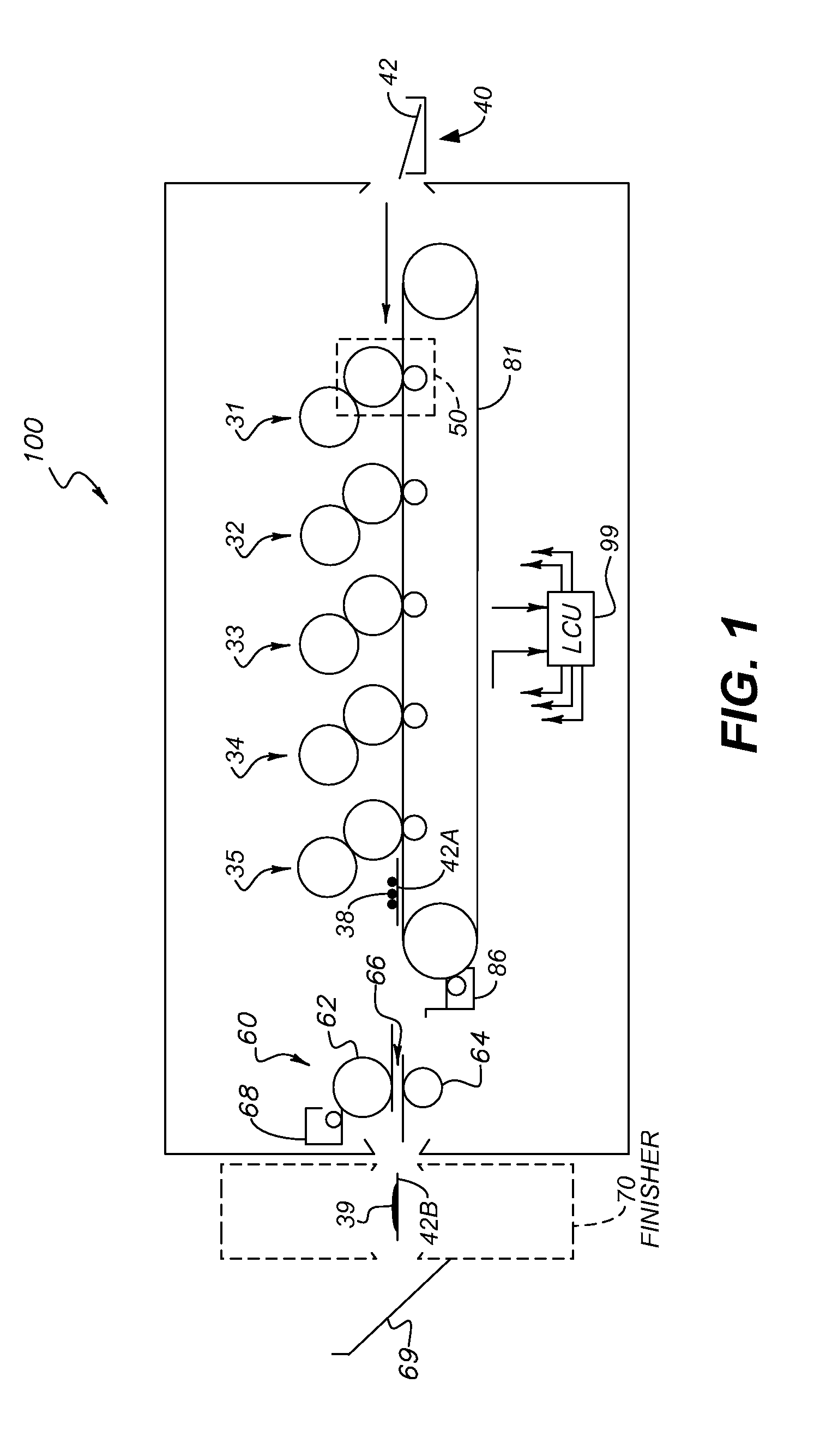
[0022]As used herein, “toner particles” are particles of one or more material(s) that are transferred by an EP printer to a receiver to produce a desired effect or structure (e.g. a print image, texture, pattern, or coating) on the receiver. Toner particles can be ground from larger solids, or chemically prepared (e.g. precipitated from a solution of a pigment and a dispersant using an organic solvent), as is known in the art. Toner particles can have a range of diameters, e.g. less than 8 μm, on the order of 10-15 μm, up to approximately 30 μm, or larger (“diameter” refers to the volume-weighted median diameter, as determined by a device such as a Coulter Multisizer).

[0023]“Toner” refers to a material or mixture that contains toner particles, and that can form an image, pattern, or coating when deposited on an imaging member including a photoreceptor, a photoconductor, or an electrostatically-charged or magnetic surface. Toner can be transferred from the imaging member to a receive...


PUM


Abstract

Carrier particles are removed from a rotatable photoreceptor in an electrophotographic printer. A development member is rotated to selectively supply toner from a developer supply to the photoreceptor, the developer including toner particles and carrier particles, and at least one carrier particle from the developer is drawn into contact with the photoreceptor while the development member supplies toner to the photoreceptor. A skive is moved into proximity with the surface of the photoreceptor and energized so that it provides an electric or magnetic field when in proximity with the surface of the photoreceptor. Carrier particles on the photoreceptor are thus transported into proximity with the skive. After carrier particles are transported into proximity with the skive, the skive is retracted from the photoreceptor, so that the transported carrier particles are drawn away from the photoreceptor;

Description

CROSS-REFERENCE TO RELATED APPLICATIONS[0001]Reference is made to commonly assigned, co-pending U.S. patent application Ser. No. 12 / 915,126, filed Oct. 29, 2010, entitled “CONTROLLING ELECTROPHOTOGRAPHIC DEVELOPER ENTERING TONING ZONE,” by Donald S. Rimai, et al, the disclosure of which is incorporated by reference herein.FIELD OF THE INVENTION[0002]This invention pertains to the field of electrophotographic printing and more particularly to removing carrier particles from a photoreceptor.BACKGROUND OF THE INVENTION[0003]Electrophotography is a useful process for printing images on a receiver (or “imaging substrate”), such as a piece or sheet of paper or another planar medium, glass, fabric, metal, or other objects as will be described below.[0004]In this process, an electrostatic latent image is formed on a photoreceptor by uniformly charging the photoreceptor and then discharging selected areas of the uniform charge to yield an electrostatic charge pattern corresponding to the des...

Claims


Application Information

Patent Timeline
Patent Type & Authority Applications(United States)
IPC IPC(8): G03G15/095
CPCG03G21/0047
Inventor RIMAI, DONALD S.
Owner EASTMAN KODAK CO
Why Eureka
Try Eureka