Photoelectric rechargeable gas detection alarm instrument

A gas detection and alarm technology, which is applied to alarms, photovoltaic power generation, electrical components, etc., can solve the problems of increasing battery capacity, limited battery capacity, and prolonging working time, so as to enhance light intensity, improve charging efficiency, and prolong working time. the effect of time

Pending Publication Date: 2020-02-11
盟莆安电子(上海)有限公司 +1
View PDF0 Cites 0 Cited by
  • Summary
  • Abstract
  • Description
  • Claims
  • Application Information

AI Technical Summary

Problems solved by technology

At present, the power supply of portable gas detectors and the backup power supply of fixed gas detectors and alarms are both composed of batteries, but the battery capacity is limited and needs to be charged regularly
In order to prolong the working time, the battery capacity needs to be increased, and the cost increases
At the same time, due to the limitation of battery energy density and instrument volume, the increase of battery capacity is limited.

Method used


Image

  • Photoelectric rechargeable gas detection alarm instrument
  • Photoelectric rechargeable gas detection alarm instrument
  • Photoelectric rechargeable gas detection alarm instrument

Examples


Embodiment 1

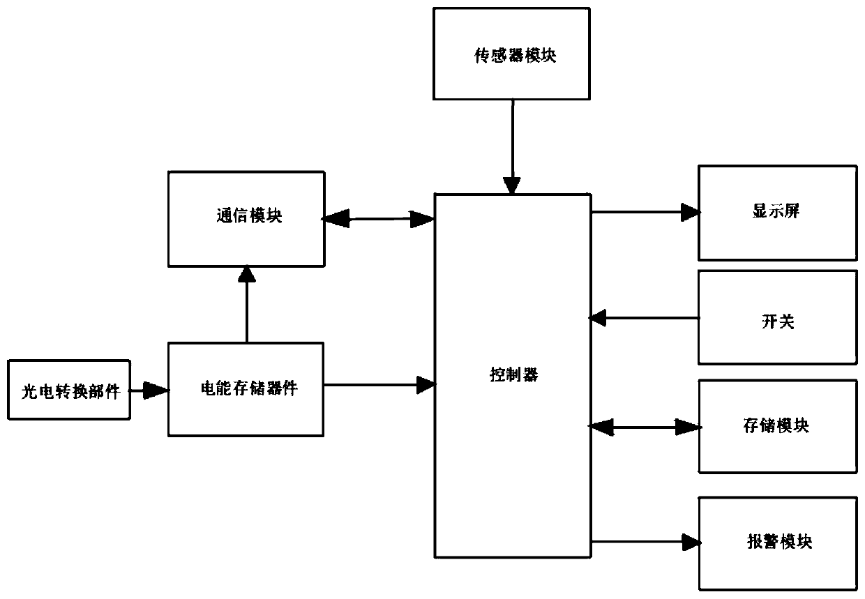
[0036] as attached Figure 1-5 The shown photoelectric rechargeable gas detection alarm includes an alarm body, the alarm body includes a housing 1, and the outer wall of one side of the housing 1 is provided with a sensor module 2, an alarm module, a display screen 4, A switch 5, the housing 1 is provided with a storage module 7, a communication module 8, a controller 6, and an electric energy storage device 9, and the electric energy storage device 9 is electrically connected to the communication module 8 and the controller 6, and the controller 6 It is also electrically connected to the communication module 8 , the storage module 7 , the sensor module 2 , the alarm module, the display screen 4 , and the switch 5 , and the electric energy storage device 9 is also electrically connected to the photoelectric conversion component 10 .

[0037] The housing 1 has a transparent structure as a whole, and its material is transparent plastic. The photoelectric conversion component 10...

Embodiment 2

[0044] as attached Figure 6 As shown, the structure of this embodiment is basically the same as that of Embodiment 1. The difference between this embodiment and Embodiment 1 is that the housing 1 is not provided with a transparent structure, and the photoelectric conversion component 10 is bonded by structural glue. The flexible thin film solar cell on the outer wall of any side wall of the housing 1 that is not provided with the display screen 4, preferably, the outer wall of the side wall with a larger area can be selected to bond the flexible thin film solar cell, thereby increasing the available The area of ​​the bonded flexible thin film solar cell increases the light receiving area. A transparent protective layer 12 is provided on the surface of the flexible thin film solar cell, and the transparent protective layer 12 is polyethylene coating or epoxy resin coating, and the transparent protective layer 12 can protect the flexible thin film solar cell.

Embodiment 3

[0046] as attached Figure 7-8 As shown, the structure of this embodiment is basically the same as that of Embodiment 1. The difference between this embodiment and Embodiment 1 is that the casing 1 is not provided with a transparent structure, and the photoelectric conversion component 10 is arranged outside the casing 1 The solar paint layer on the surface is provided with a transparent protective layer 12 on the surface of the solar paint layer. The transparent protective layer 12 is a polyethylene coating or an epoxy resin coating. The transparent protective layer 12 can protect the solar paint layer. The solar paint layer arranged on the outer surface of the casing 1 can fully utilize the appearance area of ​​the instrument to maximize the absorption of light energy.


PUM


Abstract

The invention discloses a photoelectric rechargeable gas detection alarm instrument, which comprises a shell body, wherein a sensor module, an alarm module, a display screen and a switch are arrangedon the outer wall of one end of the shell body; a storage module, a communication module, a controller and a storage battery are arranged in the shell body, the storage battery is electrically connected with the communication module and the controller, the controller is further electrically connected with the communication module, the storage module, the sensor module, the alarm module, the display screen and the switch, the storage battery is further electrically connected with a photoelectric conversion component, and the shell body is provided with or not provided with a transparent structure or not; when the shell body is provided with the transparent structure, the photoelectric conversion component is arranged at a position, corresponding to the transparent structure, in the shell body; and when the shell body is not provided with the transparent structure, the photoelectric conversion part is connected to the outside of the shell body. The photoelectric rechargeable gas detection alarm instrument adds a photoelectric charging function to a gas detection instrument without increasing battery capacity, receives illumination energy in the environment, supplements energy to theinstrument, and prolongs the service hours of the instrument.

Description

technical field [0001] The invention relates to the field of gas detection devices, in particular to a photoelectric charging type gas detection and alarm instrument. Background technique [0002] The raw materials in industrial production and the intermediate products in the production process contain toxic, harmful, flammable and explosive gases. Because these gases cannot be seen intuitively, it is difficult to find when leaking, which poses serious safety hazards to staff and production facilities. Gas detection instruments can detect low-concentration gases through electrochemical, catalytic combustion, infrared, PID and other sensors, and provide early warning of leakage. At present, the power supply of portable gas detectors and the backup power supply of fixed gas detectors and alarms are all composed of batteries, but the battery capacity is limited and needs to be charged regularly. In order to prolong the working time, the battery capacity needs to be increased,...

Claims


Application Information

Patent Timeline
IPC IPC(8): G08B21/12H02H9/02H02H9/04H02J7/00H02J7/35H02S40/22
CPCG08B21/12H02J7/0042H02S40/22H02H9/02H02H9/04Y02E10/52H02J7/35G08B21/14G08B21/16
Inventor 杭益青奚庆中孙鸿涛
Owner 盟莆安电子(上海)有限公司
Why Eureka
Try Eureka