Digital receive phase lock loop with cumulative phase error correction and dynamically programmable correction rate

a phase lock loop and digital technology, applied in the direction of digital transmission, pulse automatic control, synchronisation signal speed/phase control, etc., can solve the problems of system failure, system failure, and apparent position drift of each pulse,

Inactive Publication Date: 2004-03-02
HEWLETT-PACKARD ENTERPRISE DEV LP +1
View PDF5 Cites 35 Cited by
  • Summary
  • Abstract
  • Description
  • Claims
  • Application Information

AI Technical Summary

Problems solved by technology

The problem with such a high data rate (narrow pulse width) is that the system is particularly susceptible to failure due to distortion of the data stream inherent in any transmission medium, such as cables running between offices in a large building for example.
Such variations cause jitter in the received signal, in which the time between successive pulses observed at a receiving point in the network fluctuates, causing the apparent position of each pulse to drift.
If this drift becomes excessive, the receiving device cannot maintain synchronization between the incoming data stream and its own clock, leading to complete loss of the received signal.
However, a 13.5 nS drift in a high-speed system in which the pulse width is only 50 nS, for example, often causes loss of synchronization and therefore failure.
I found that the foregoing architecture, when applied to data having a frequency of 10 MHz, was inadequate to withstand jitter of well over 10 nS, e.g., jitter of 13.5 nS.
Tha...

Method used


Image

  • Digital receive phase lock loop with cumulative phase error correction and dynamically programmable correction rate
  • Digital receive phase lock loop with cumulative phase error correction and dynamically programmable correction rate
  • Digital receive phase lock loop with cumulative phase error correction and dynamically programmable correction rate

Examples


Embodiment Construction

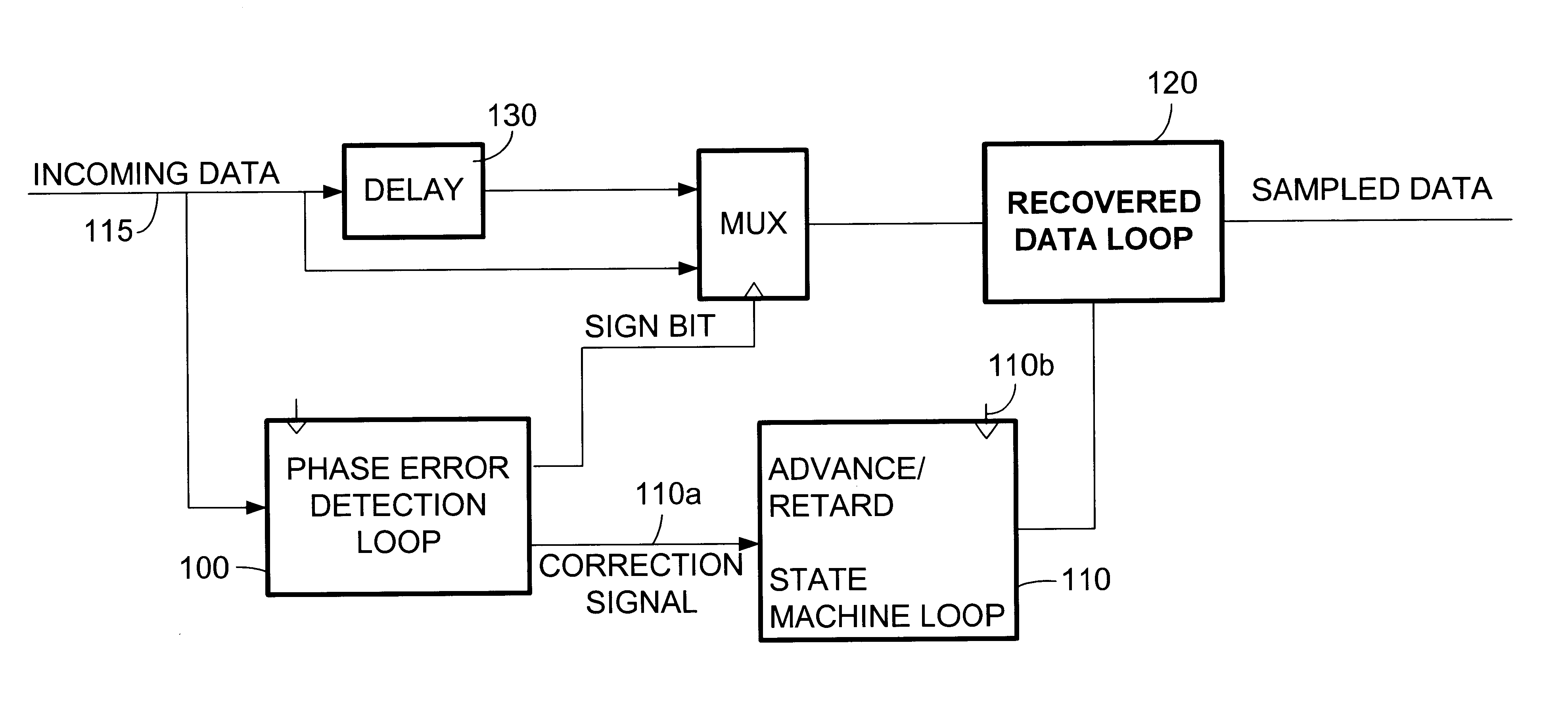
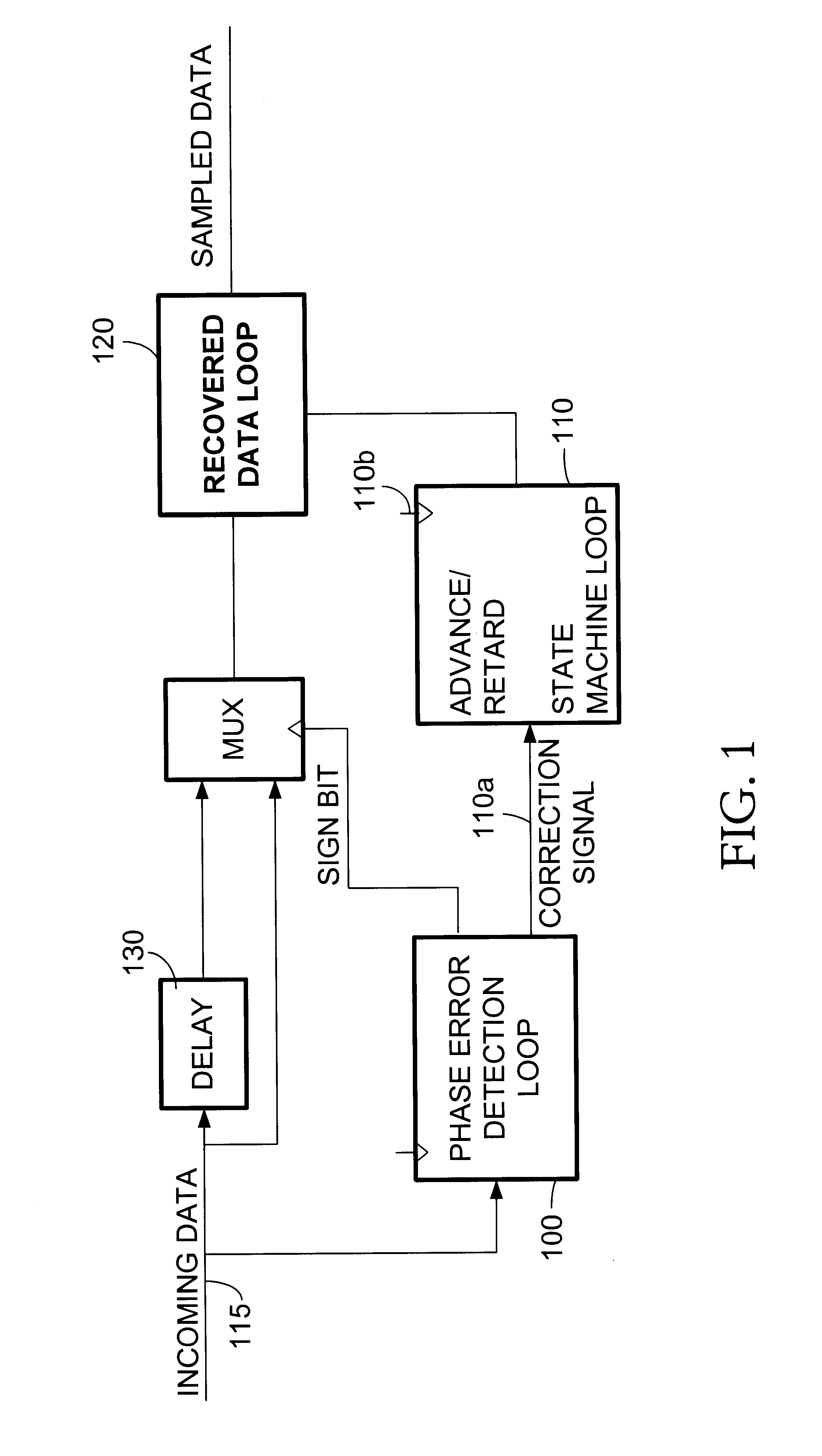
FIG. 8 illustrates the preferred embodiment of a phase lock the invention, which is a PLL including the four embodiments of FIGS. 1, 3, 4 and 5.

(1) Conversion to a Serial Bit Stream:

The incoming data stream is received on a coaxial cable which may be 100 meters long, for example. At the PLL's input terminal 801, three comparators are connected across the inner and outer conductors of the cable 801, namely a HI comparator 803, a LO comparator 805 and a ZC (zero crossing) comparator 807. The HI comparator 803 has an output that is a logic high whenever the voltage of the received data signal exceeds +250 mV, the LO comparator 805 has an output that is a logic high whenever the voltage of the received data signal falls below -250 mV while the ZC comparator 807 has an output that is a logic high whenever the voltage of the received data signal is a small voltage (.+-.5 V) near zero volts. A conventional parallel-to-serial converter 809 converts the parallel logic outputs of the comparat...


PUM


Abstract

A digital phase lock loop (PLL) for maintaining synchronization with the phase of a received data signal including a preamble and an information-containing data frame, by incrementing a state machine through an internal cyclic count, each cycle thereof including a center count tending to coincide with center regions of the successive pulses and an edge count tending to coincide with edges of the successive pulses. The PLL selects a current sample of the signal whenever the internal count reaches the predetermined center count value. The state machine internal count is updated in accordance with a cumulative phase error obtained by summing the phase errors detected over successive edges between each edge and the corresponding center count. The interval over which the cumulative phase error is computed depends upon the number of received edges during the preamble and depends upon elapsed time during the data frame.

Description

1. Technical FieldThe invention is related to digital communication devices and in particular to a receive digital phase lock loop.2. Background ArtDigital communications such as those provided in a wide area network (WAN) or local area network (LAN) of personal computers (for example) are constantly being improved to operate at higher data rates. For example, there is considerable interest in developing networks capable of operating at a clock frequency of 10 MHz, corresponding to a pulse width of 50 nanoseconds (nS). Preferably, the data transmitted on the network is Manchester encoded. The problem with such a high data rate (narrow pulse width) is that the system is particularly susceptible to failure due to distortion of the data stream inherent in any transmission medium, such as cables running between offices in a large building for example. The speed at which the data-containing signal travels through the cable is affected by a number of things including stray capacitances th...

Claims


Application Information

Patent Timeline
IPC IPC(8): H03L7/099H03L7/08H04L7/033H04L7/04
CPCH03L7/0992H04L7/0331H04L7/046
Inventor STINE, ERIC
Owner HEWLETT-PACKARD ENTERPRISE DEV LP
Why Eureka
Try Eureka