Blade ring segment having an annular space delimiting surface having a wavy height profile and a method for manufacturing same

a technology of annular space and delimiting surface, which is applied in the field of turbines, can solve problems such as negative influence on the flow conditions of the annular spa

Active Publication Date: 2013-09-19
MTU AERO ENGINES GMBH
View PDF6 Cites 2 Cited by
  • Summary
  • Abstract
  • Description
  • Claims
  • Application Information

AI Technical Summary

Benefits of technology

[0005]It is an object of the present invention to provide a method for machining a workpiece, while avoiding the corresponding problems, such as those defined in the related art, and this method is to be used in particular for machining blade ring segments for blade rings of turbomachines. In addition, blade ring segments and / or blade rings are to be provided in which the problem of steps between adjacent annular space delimiting surfaces on shrouds is avoided.
[0007]Accordingly, an elevated profile and therefore less material removal may be provided in areas which interact with the electrode for a longer period of time or starting at an earlier point in time, whereas in areas which interact with the electrode later or for a shorter period of time, there is greater material removal or a corresponding valley or a reduced height profile.

Problems solved by technology

Due to the electrochemical machining of the shroud while the electrode is being moved over the Z-shaped end of the shroud, there is thus removal of different amounts of material along the Z-shaped edge, so that in the case of adjacent blade ring segments, steps appear between the annular space delimiting surface, which results in a negative influence on the flow conditions in the annular space.

Method used


Image

  • Blade ring segment having an annular space delimiting surface having a wavy height profile and a method for manufacturing same
  • Blade ring segment having an annular space delimiting surface having a wavy height profile and a method for manufacturing same
  • Blade ring segment having an annular space delimiting surface having a wavy height profile and a method for manufacturing same

Examples


Embodiment Construction

[0021]Additional advantages, characteristics and features of the present invention will become explicit in the following detailed description of one exemplary embodiment. However, the present invention is not limited to this exemplary embodiment.

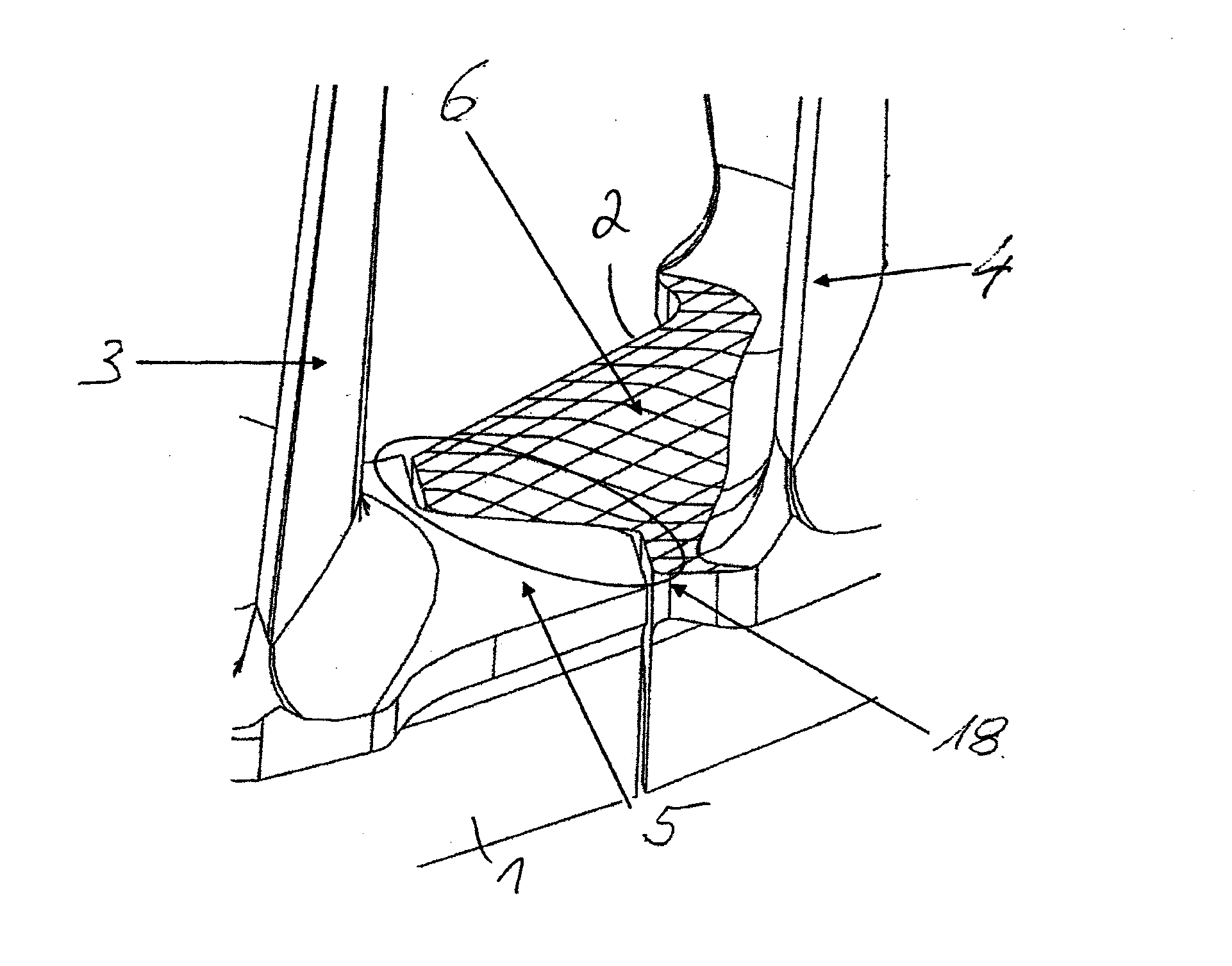
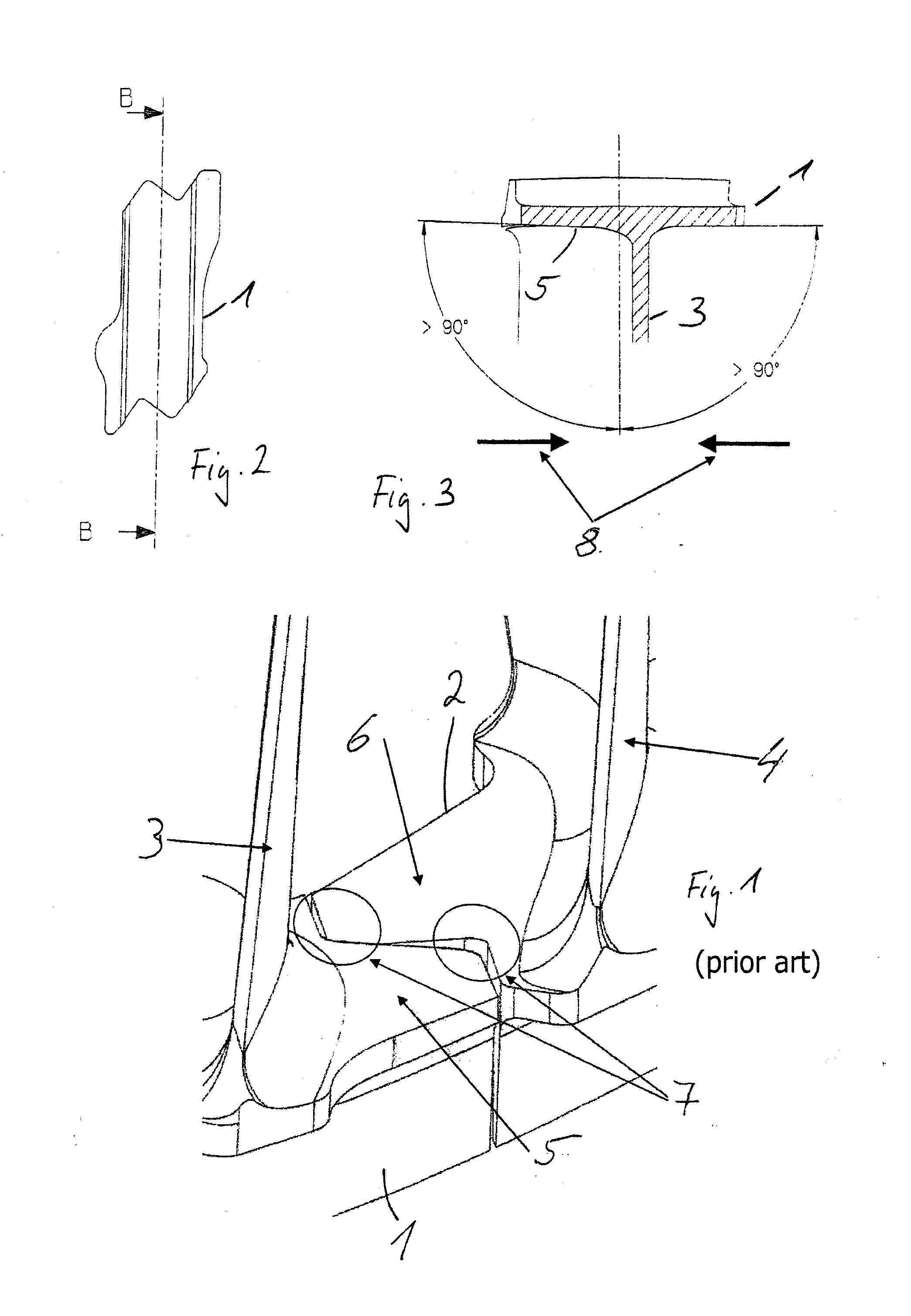
[0022]FIG. 1 shows a part of a blade ring having two adjacent blade ring segments 1 and 2, such as those used in turbomachines, for example, gas turbines or aircraft engines. In the shown exemplary embodiment, adjacent blade ring segments 1 and 2 have two shrouds having annular space delimiting surfaces 5 and 6, which are designed to be complementary to one another at their end edges in a Z shape, so that blade ring segments 1 and 2 are joined together in a form-locked manner. This Z-shaped profile is usually provided on the outer shrouds, FIG. 1 being rotated by 180° for a better representation, so the outer shroud is shown at the bottom.

[0023]Blade ring segments 1 and 2 each have a blade profile 3 and 4, which are situated obliquely or tra...


PUM

PropertyMeasurementUnit
diameteraaaaaaaaaa
diameteraaaaaaaaaa
diameteraaaaaaaaaa

Abstract

A method for machining a workpiece. An electrode is moved linearly in the direction of the workpiece to cause material to be removed from the workpiece, at least one end of a surface of the workpiece running obliquely to a guide edge of the electrode machining this surface. The electrode is moved at least partially with the electrode surface parallel to the surface, so that during the approach to the workpiece, areas of the workpiece having an irregular edge machined at a different intensity are formed, the difference in intensity of machining on the edge of the surface to be machined being compensated in that the surface to be machined is provided with a height profile adapted to the shape of the end of the surface to be machined. A blade ring segment and blade ring is also disclosed.

Description

[0001]This claims the benefit of European Patent Application EP 12159601.9, filed Mar. 15, 2012 and hereby incorporated by reference herein.[0002]The present invention relates to a method for machining a workpiece, in which an electrode is situated at a distance from the workpiece to be machined and is moved linearly in the direction of the workpiece to be machined to cause material to be removed from the workpiece during the approach to the workpiece, at least one end or one section of one end of a surface of the workpiece to be machined running obliquely to a guide edge of the electrode machining this surface, and the electrode is moved at least partially with the electrode surface parallel to the surface to be machined, so that, during the approach to the workpiece, areas of the workpiece having an irregular edge occur as a result of being machined at a different intensity. Furthermore, the present invention relates to blade ring segments for a blade ring of a turbomachine and a ...

Claims


Application Information

Patent Timeline
Patent Type & Authority Applications(United States)
IPC IPC(8): F01D5/02B23H1/00
CPCB23H1/00F01D5/02B23H3/00B23H9/10Y02T50/673F01D5/225F01D25/28F05D2230/10F01D5/143F05B2230/101C25F3/00Y02T50/60B23P15/02F05D2220/323F05D2230/11F05D2250/20F05D2250/611
Inventor PERNLEITNER, MARTINBICHLMAIER, CHRISTIANZSCHERP, CARSTEN
Owner MTU AERO ENGINES GMBH
Why Eureka
Try Eureka