Method of making a magnetoresistive reader structure

a reader structure and magnetoresistive technology, applied in the field of making magnetoresistive reader structures, can solve the problems of preventing proper stabilization during use and the inability to be lifted off, and achieve the effect of facilitating the removal of excess material

Inactive Publication Date: 2010-01-05
WESTERN DIGITAL TECH INC
View PDF13 Cites 11 Cited by
  • Summary
  • Abstract
  • Description
  • Claims
  • Application Information

AI Technical Summary

Benefits of technology

[0007]In one embodiment, a method of forming a magnetoresistive (MR) read sensor includes providing a MR sensor stack within a dielectric and removing a portion of the MR sensor stack and the dielectric to define a track width of the MR read sensor. Depositing a hard bias layer on both sides of the MR sensor stack fills voids defined by the portion removed. Applying a photoresist above the hard bias layer and over the MR sensor stack facilitates removing excess material of the hard bias layer outside of the photoresist. Chemical mechanical polish (CMP) may then be used to remove the hard bias material on top of the track width region and to planarize the hard bias layer.
[0008]For one embodiment, a method of forming a MR read sensor includes providing a bottom shield with a MR sensor stack deposited on the bottom shield. Depositing a hard bias layer fills wells on each side of the MR sensor stack. Removing excess material of the hard bias layer utilizes a photoresist above the hard bias layer to protect areas of the hard bias layer that require relatively less material removal.

Problems solved by technology

For example, material deposited to form the hard magnetic bias structure may remain above the MR sensor without any ability to be lifted off due to a photoresist lacking sufficient thickness as a result of its poor mill resistance at small track width.
Further, attempts to remove unwanted portions of the hard magnetic bias structure tend to create unevenness or thinning of the hard magnetic bias structure and thereby prevent proper stabilization during use.

Method used


Image

  • Method of making a magnetoresistive reader structure
  • Method of making a magnetoresistive reader structure
  • Method of making a magnetoresistive reader structure

Examples


Embodiment Construction

[0021]In the following, reference is made to embodiments of the invention. However, it should be understood that the invention is not limited to specific described embodiments. Instead, any combination of the following features and elements, whether related to different embodiments or not, is contemplated to implement and practice the invention. Furthermore, in various embodiments the invention provides numerous advantages over the prior art. However, although embodiments of the invention may achieve advantages over other possible solutions and / or over the prior art, whether or not a particular advantage is achieved by a given embodiment is not limiting of the invention. Thus, the following aspects, features, embodiments and advantages are merely illustrative and, unless explicitly present, are not considered elements or limitations of the appended claims.

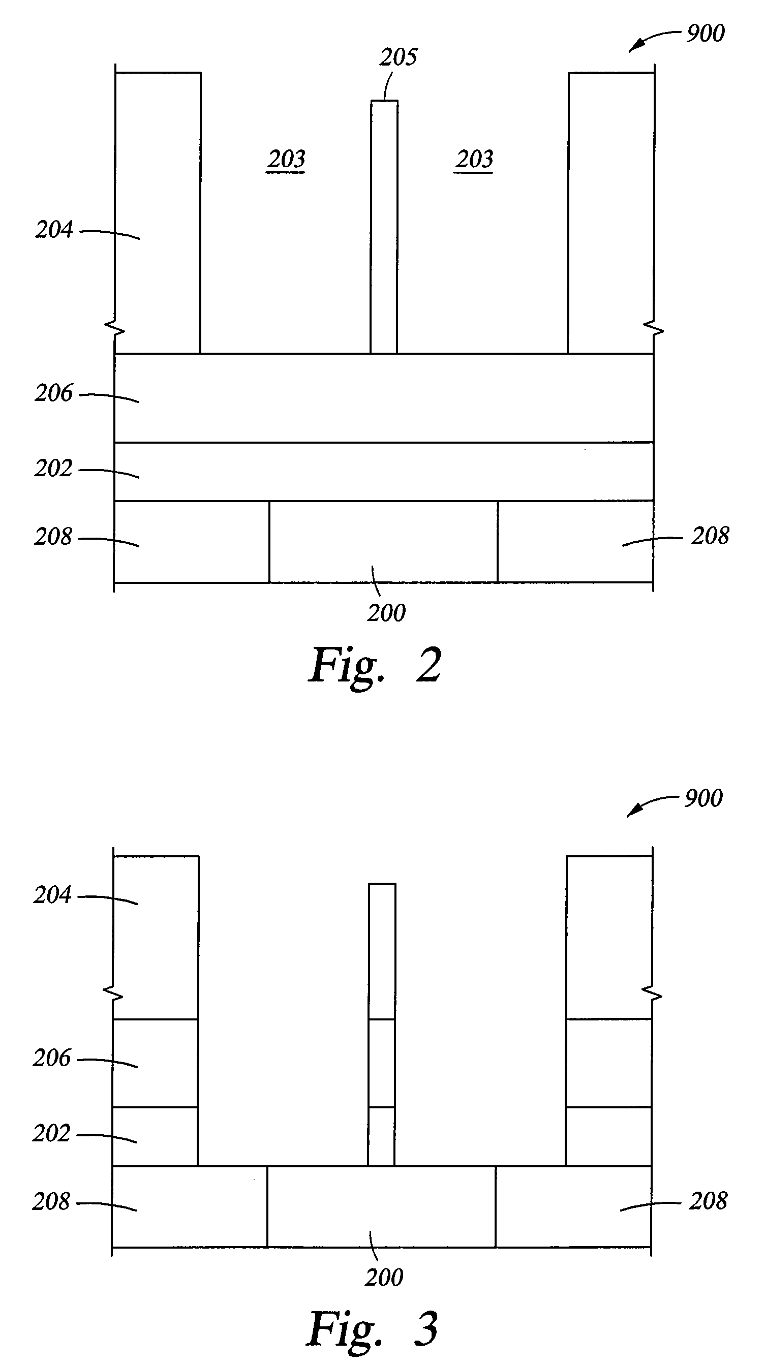
[0022]Embodiments of the invention relate to methods of making a magnetoresistive sensor. The method includes defining a track wi...


PUM

PropertyMeasurementUnit
widthaaaaaaaaaa
widthaaaaaaaaaa
thicknessaaaaaaaaaa

Abstract

A method of making a magnetoresistive sensor includes defining a track width of a magnetoresistive element stack of the sensor. Further, processes of the method enable depositing of hard magnetic bias material on each side of the stack. These processes may permit both milling of excess depositions of the material outside of regions where the hard magnetic bias material is desired via use of a photoresist and making the material have a planar surface via chemical mechanical polishing, which also removes the material on top of the stack. The method includes removing excess material outside of the photoresist, wherein the excess material includes part of the hard bias layer, while a portion of the hard bias layer remains directly above the MR sensor stack.

Description

BACKGROUND OF THE INVENTION[0001]1. Field of the Invention[0002]Embodiments of the invention generally relate to methods of making a magnetoresistive reader structure for sensing data stored on magnetic media.[0003]2. Description of the Related Art[0004]In an electronic data storage and retrieval system, a magnetic head typically includes a reader portion having a magnetoresistive (MR) sensor for retrieving magnetically encoded information stored on a magnetic recording medium or disk. The MR sensor includes multiple layers and operates based on a change of resistance of the MR sensor in the presence of a magnetic field. During a read operation, a bias current is passed through the MR sensor. Magnetic flux emanating from a surface of the recording medium causes rotation of a magnetization vector of a sensing or free layer of the MR sensor, which in turn causes the change in resistance of the MR sensor. The change in resistance of the read element is detected by passing a sense curre...

Claims


Application Information

Patent Timeline
Patent Type & Authority Patents(United States)
IPC IPC(8): G11B5/127G11B5/33H04R31/00
CPCG01R33/098G11B5/3163G11B5/398Y10T29/49041Y10T29/49043Y10T29/49046Y10T29/49044
Inventor ARAKI, SATORUHONG, YINGJAYASEKARA, WIPULJIANG, MING
Owner WESTERN DIGITAL TECH INC
Why Eureka
Try Eureka