Internal combustion engine with hydraulic device for adjusting the rotation angle of a camshaft in relation to a crankshaft

a technology of hydraulic device and internal combustion engine, which is applied in the direction of valve details, valve arrangement, valve drive, etc., can solve the problems of large manufacturing cost of sintered components by material removal process, undesired external oil leakage, etc., to prevent oscillation of stator, increase bending strength and compressive strength, and reduce overall mass

Active Publication Date: 2007-10-23
SCHAEFFLER TECH AG & CO KG
View PDF8 Cites 5 Cited by
  • Summary
  • Abstract
  • Description
  • Claims
  • Application Information

AI Technical Summary

Benefits of technology

[0011]The number of sintered components being produced is thus decreased while the material removal process is simplified and the risk of external oil leaks is reduced as a result of the absence of porous sintered parts.
[0023]A hydraulic device according to the present invention is lightweight and easier to manufacture (less material removal) as a result of a decreased number of components so that manufacturing costs are reduced and the assembly is simplified. The need for previously required impregnation with synthetic resin or vapor treatment for sealing sintered material is eliminated as provision of sintered material is no longer required.

Problems solved by technology

As a result, the hydraulic device is very massive.
In addition, manufacturing costs for making the sintered components by the material removal process are extensive, and undesired external oil leaks can be experienced as a consequence of the porosity of the sintered components.
Another reason for making the components of hydraulic devices heavy and massive is the belief that thin wall thicknesses in sintering metallurgy would cause problems as far as density distribution, strength and stiffness are concerned, especially when the wall thickness fluctuates, and that complex shapes with different fill heights can normally be realized only by using expensive slides in the tool.
Hydraulic devices made by a material removing process encounter similar problems.
This approach has, however, the drawback that the leakage gap increases in view of the presence of different thermal expansion coefficients when the components heat up, resulting in excessive leaking.
Moreover, aluminum is subjected to greater deformation than steel or iron under load when same dimensions are involved.
In particular, the use of screw fasteners to bolt the individual parts together requires the provision of large enough gaps to accommodate the deformation.
The need for screw fasteners, however, not only also complicates the assembly and incurs added costs but also adversely affects the force flux.

Method used


Image

  • Internal combustion engine with hydraulic device for adjusting the rotation angle of a camshaft in relation to a crankshaft
  • Internal combustion engine with hydraulic device for adjusting the rotation angle of a camshaft in relation to a crankshaft
  • Internal combustion engine with hydraulic device for adjusting the rotation angle of a camshaft in relation to a crankshaft

Examples


Embodiment Construction

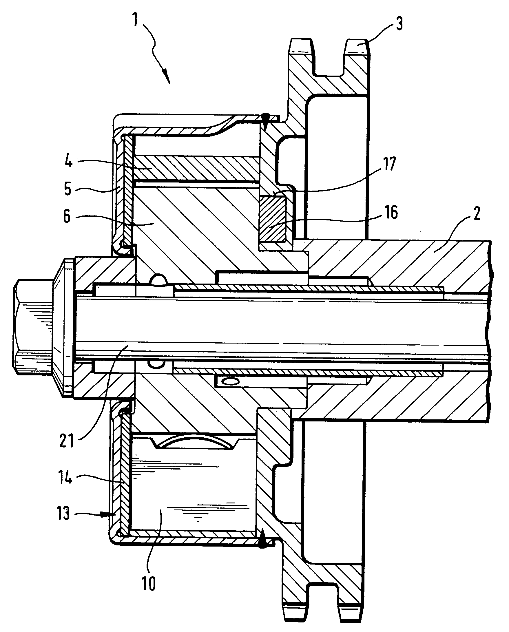
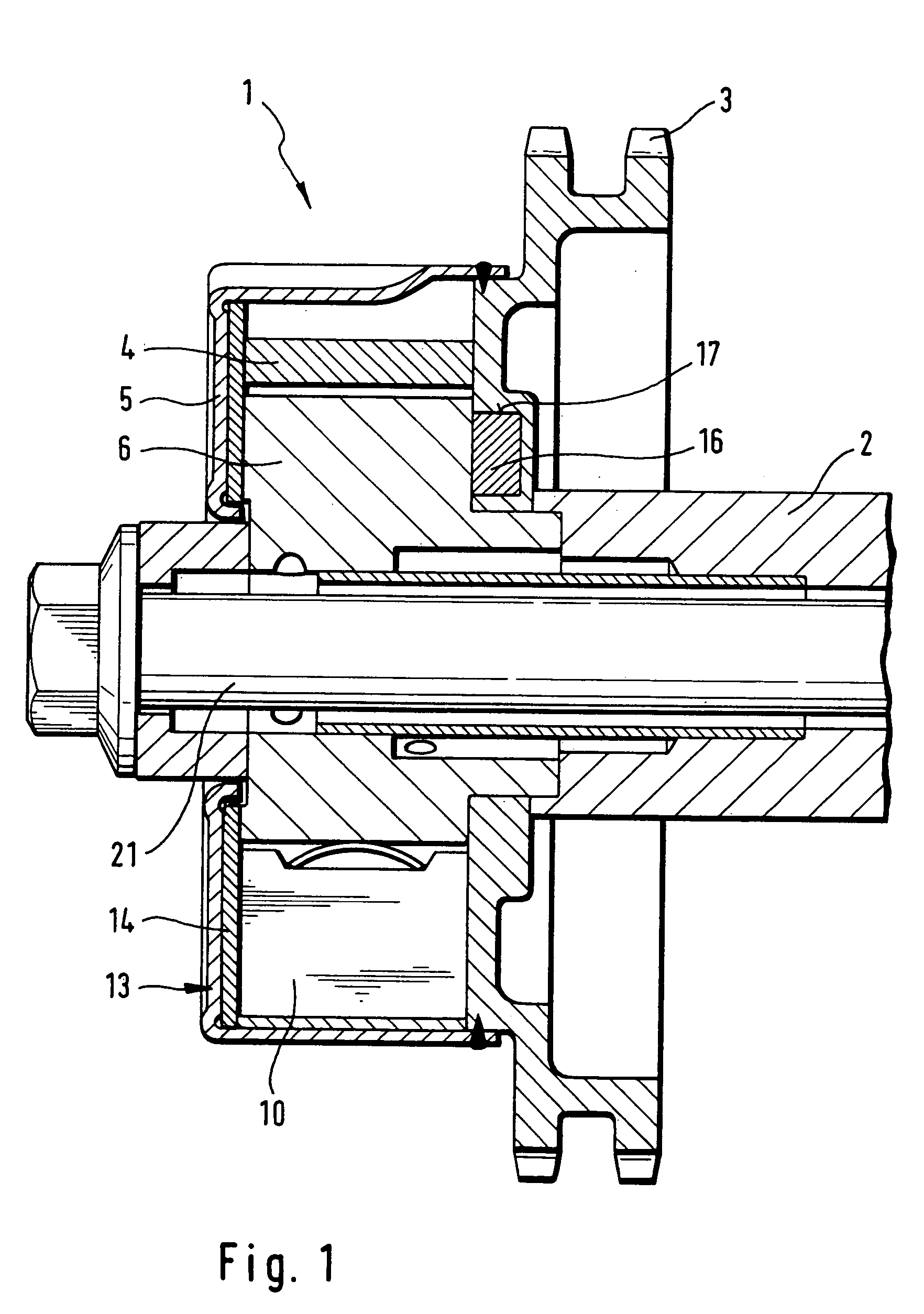
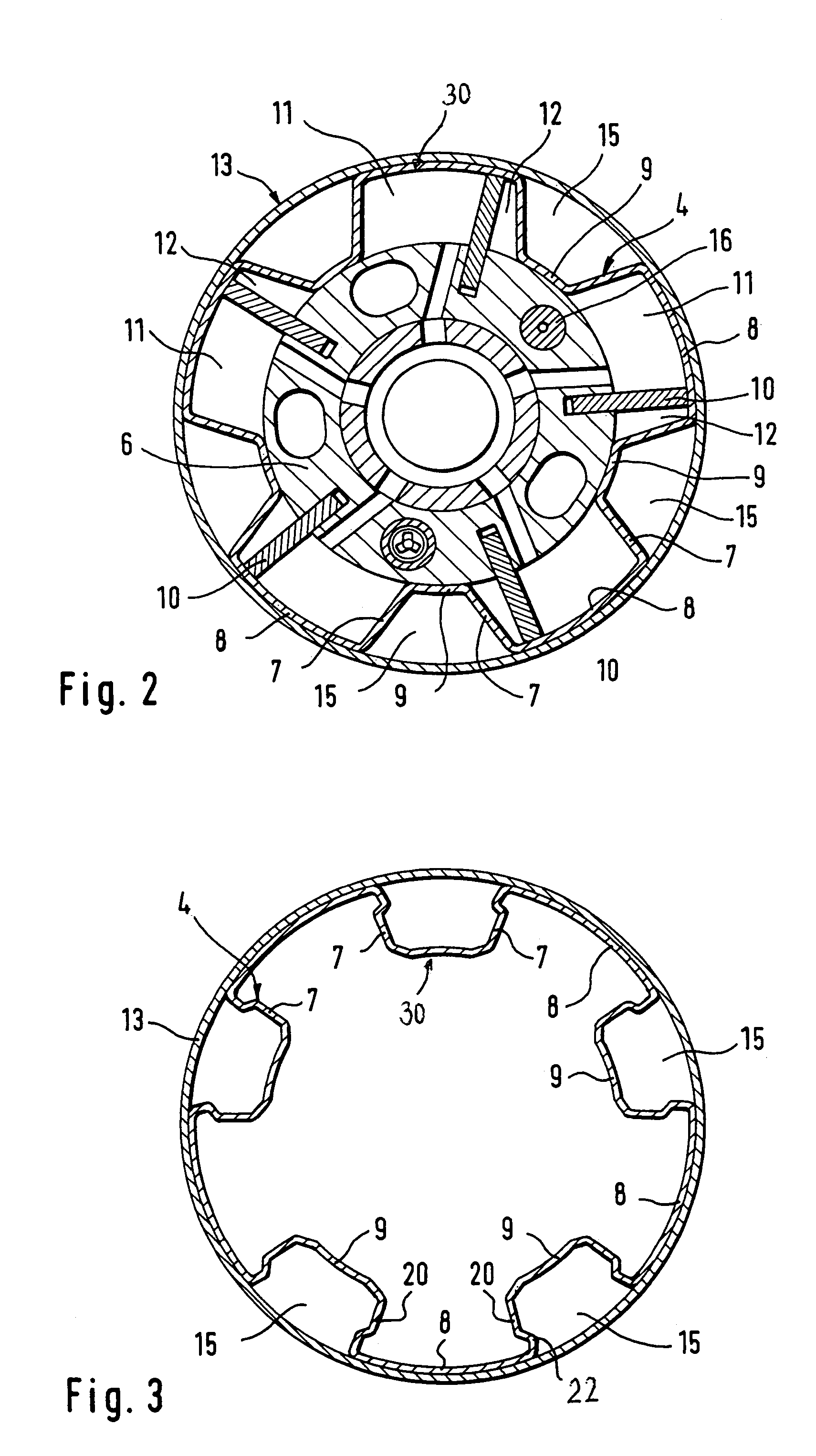
[0034]Throughout all the Figures, same or corresponding elements are generally indicated by same reference numerals. These depicted embodiments are to be understood as illustrative of the invention and not as limiting in any way. It should also be understood that the drawings are not necessarily to scale and that the embodiments are sometimes illustrated by graphic symbols, phantom lines, diagrammatic representations and fragmentary views. In certain instances, details which are not necessary for an understanding of the present invention or which render other details difficult to perceive may have been omitted.

[0035]This is one of two applications both filed on the same day. Both applications deal with related inventions. They are commonly owned and have the different inventive entity. Both applications are unique, but incorporate the other by reference. Accordingly, the following U.S. patent application is hereby expressly incorporated by reference: “INTERNAL COMBUSTION ENGINE WITH...


PUM


Abstract

A hydraulic device in an internal combustion engine for adjusting a rotation angle of a camshaft in relation to a crankshaft includes a tubular stator and a rotor connected in fixed rotative engagement with the camshaft and having plural vanes in spaced apart relationship to define pressure chambers on both sides of the vanes. The stator is connected in fixed rotative engagement with a crankshaft-drive timing pulley and constructed to define with the rotor vanes the pressure chambers. The stator is made by a shaping process without material to effect a mass reduction. Pressure medium is supplied to or purged from the pressure chambers to selectively adjust the position of the rotor in relation to the stator and thereby the position of the camshaft in relation to the crankshaft.

Description

CROSS-REFERENCES TO RELATED APPLICATIONS[0001]This application claims the priority of German Patent Application, Serial No. 103 58 888.4, filed Dec. 16, 2003, pursuant to 35 U.S.C. 119(a)-(d).BACKGROUND OF THE INVENTION[0002]The present invention relates, in general, to an internal combustion engine, and more particularly to a hydraulic device of an internal combustion engine to adjust the rotation angle of a camshaft in relation to a crankshaft.[0003]Nothing in the following discussion of the state of the art is to be construed as an admission of prior art.[0004]German patent publication no. DE 101 34 320 A1 describes a hydraulic device for adjusting the phase position of a camshaft in relation to a crankshaft of an internal combustion engine. The device includes a rotor, which is configured in the form of a vane wheel secured to the camshaft and co-rotating therewith in synchronism, and a stator which is closed in fluid-tight manner by an end wall, which forms part of a housing in...

Claims


Application Information

Patent Timeline
Patent Type & Authority Patents(United States)
IPC IPC(8): F01L1/34F01L1/344F01L1/46
CPCF01L1/3442F01L1/46F01L2101/00F01L2301/00F01L1/34
Inventor WIERL, ULRICHKOHRS, MIKEOTTERSBACH, RAINERAUCHTER, JOCHENWIEHL, HERMANN
Owner SCHAEFFLER TECH AG & CO KG
Why Eureka
Try Eureka