Method and system for engine air control

a technology of engine air control and air flow, which is applied in the direction of electrical control, non-mechanical valves, instruments, etc., can solve the problems of vibration transmission torque variations and related nvh issues may persist, and may be objectionable to the vehicle operator, so as to improve fuel economy, reduce torque variations, and reduce the effect of nvh problems

Active Publication Date: 2013-09-19
FORD GLOBAL TECH LLC
View PDF9 Cites 18 Cited by
  • Summary
  • Abstract
  • Description
  • Claims
  • Application Information

AI Technical Summary

Benefits of technology

[0004]However the inventors herein have identified a potential issue with such an approach. As an example, in engines configured with a common actuator for actuating the valves of multiple cylinders (e.g., cam based valve actuators), a change in position of the common actuator will change the valve timing of all cylinders coupled to that actuator. In addition, the same change (amount, degree, and directionality) will be effected on each cylinder. However, an actuator position that improves torque variations in a first cylinder that is coupled to the common actuator may aggravate torque variations in one or more other cylinders coupled to the actuator. Consequently, even with the valve timing adjustment, torque variations and related NVH issues may persist. Overall, engine performance may be degraded.
[0008]In this way, a common actuator may be used to vary the valve timing of two or more cylinders and address cylinder-to-cylinder torque variations. By addressing the torque imbalance using camshaft adjustments, an amount of spark retard required to address the torque imbalance may be reduced, thereby improving fuel economy. By reducing torque variations arising during engine idling conditions, NVH issues may be reduced and engine performance may be improved.

Problems solved by technology

The torque variations may then be transmitted to the engine mounting system leading to vibration transmission and related NVH issues.
At certain frequencies, the vibration may be objectionable to the vehicle operator.
However the inventors herein have identified a potential issue with such an approach.
Consequently, even with the valve timing adjustment, torque variations and related NVH issues may persist.
Overall, engine performance may be degraded.
However, if the desired camshaft adjustment is outside the determined limit, then it may not be physically possible for the camshaft to switch between the positions in the allotted time.
Herein, the third and fourth positions may have a smaller separation and may not, by themselves, be able to address the torque variation.

Method used


Image

  • Method and system for engine air control
  • Method and system for engine air control
  • Method and system for engine air control

Examples


Embodiment Construction

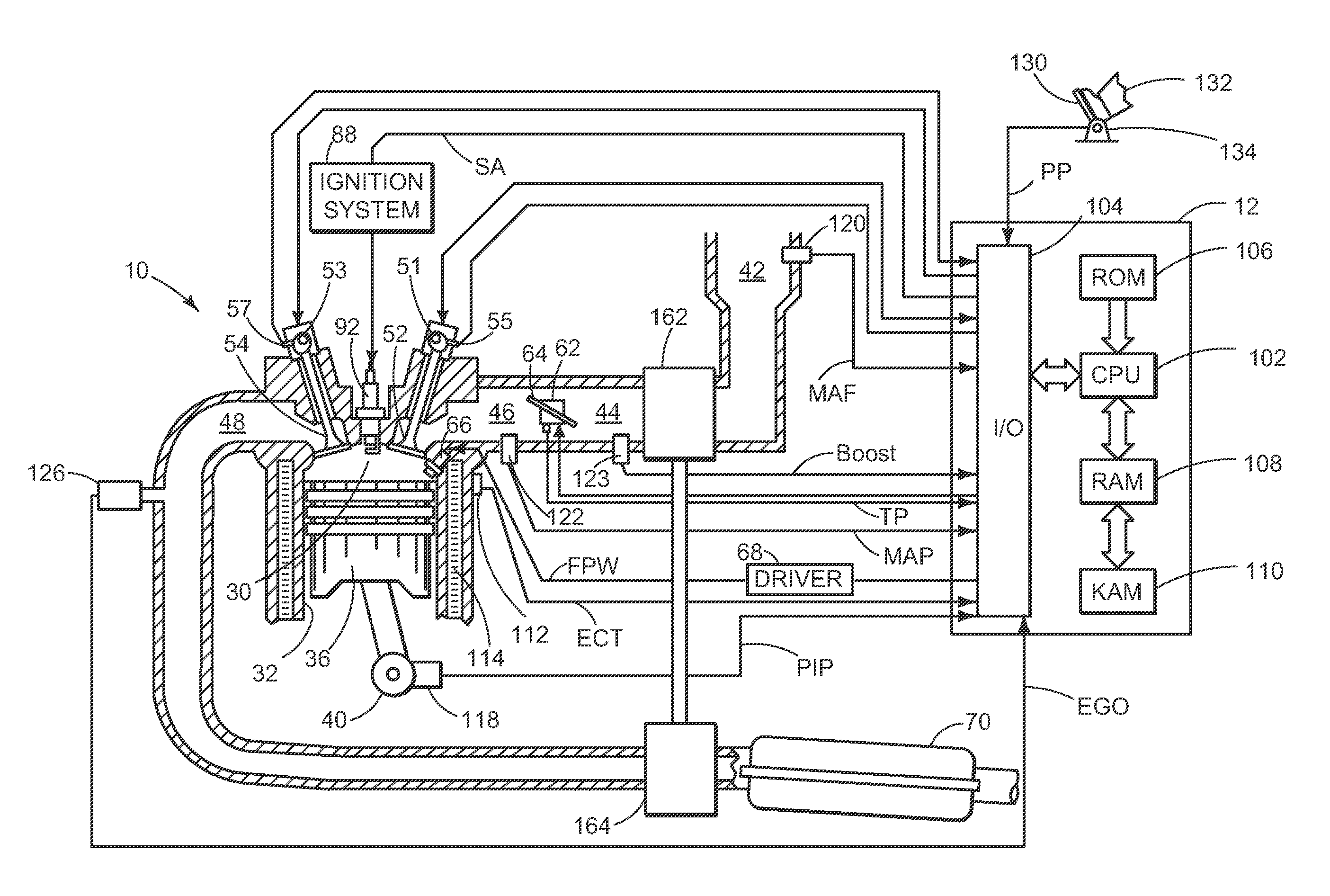
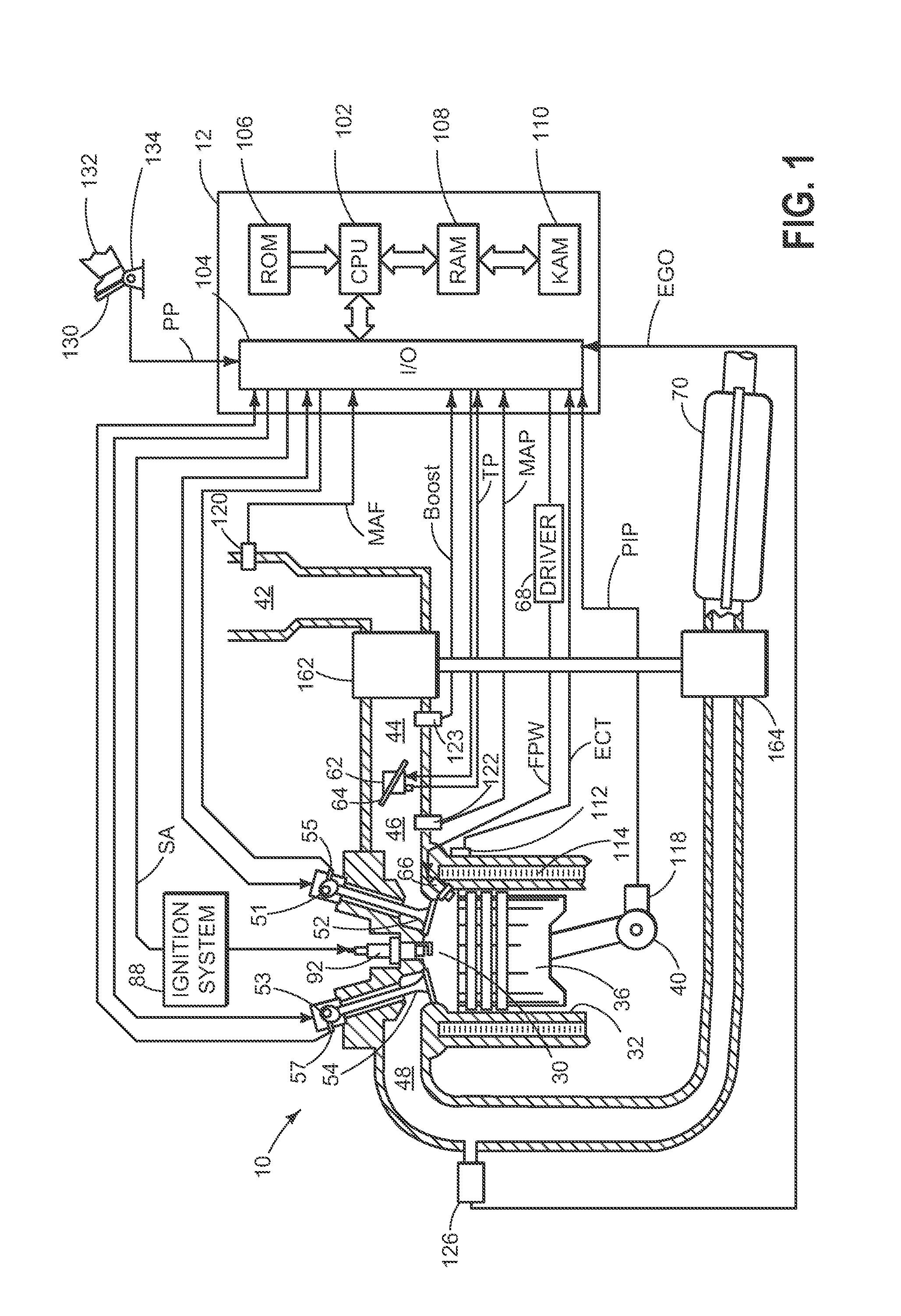
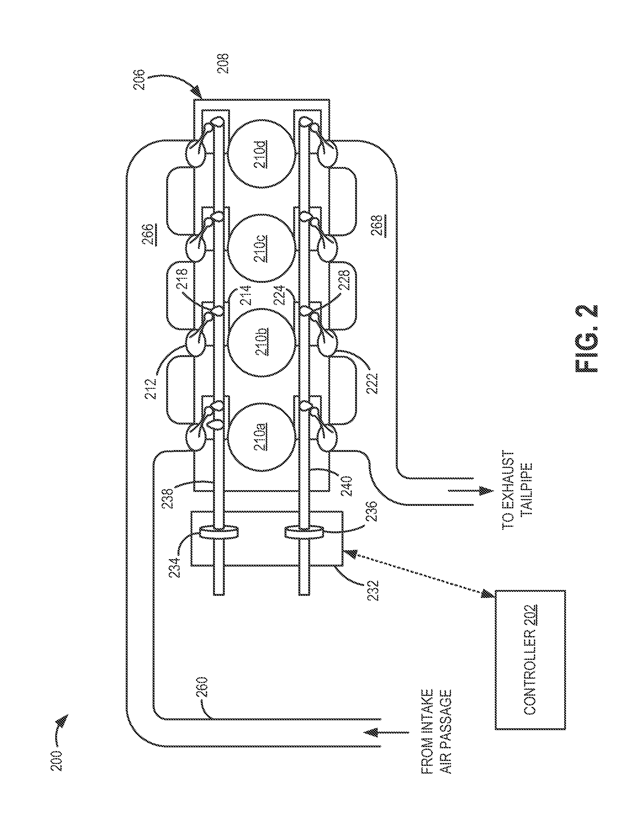
[0014]Methods and systems are provided for adjusting a valve timing of multiple engine cylinders (such as in the engine of FIG. 1) by operating a common actuator (such as the camshaft of FIG. 2). The position of a camshaft may be adjusted during engine idling conditions on a cylinder-by-cylinder basis, to reduce torque variations between the cylinders coupled to the camshaft. In particular, during any given engine cycle, the camshaft may be shifted to a first position when a first cylinder coupled to the camshaft fires, and then to a second position when a second cylinder coupled to the camshaft fires, and so on. A controller may be configured to perform a control routine, such as the example routine of FIG. 3, to adjust a position of the camshaft within camshaft limits to address torque imbalances between the cylinders. If the adjustment is not sufficient to address the torque imbalance (e.g., the adjustment is physically limited), the controller may use additional spark timing adj...


PUM


Abstract

Methods and systems are provided for reducing idling torque imbalances between cylinders by actuating a common camshaft to which the cylinders are coupled. The camshaft may be adjusted within camshaft limits during each combustion event of each cylinder. In this way, idling NVH issues may be addressed.

Description

FIELD[0001]The present application relates to methods and systems for controlling an engine operation.BACKGROUND AND SUMMARY[0002]At idle speed conditions, engine combustion may have substantial variation. The variation in combustion may be due to various factors including differences in fueling, charge preparation, charge distribution, and exhaust residuals between cylinders. The variation in combustion leads to variation in cylinder pressure (e.g., cylinder IMEP) as well as cylinder torque output. The torque variations may then be transmitted to the engine mounting system leading to vibration transmission and related NVH issues. At certain frequencies, the vibration may be objectionable to the vehicle operator.[0003]One approach to address the engine idling cylinder torque variation is shown by Nakasaka in US 2007 / 0163547. Therein, variation in intake air amount between cylinders is determined and a variable valve device is adjusted accordingly. Specifically, an operating angle an...

Claims


Application Information

Patent Timeline
Patent Type & Authority Applications(United States)
IPC IPC(8): F01L1/34F01L25/08
CPCF02D13/02F02D13/08F02D41/0085F02D41/08Y02T10/42F02D41/16F02D41/0002F02D2041/001F02D41/1498F02B2075/125F02D13/0219Y02T10/12Y02T10/40F02D23/00F02D41/0097F01L13/0063
Inventor GLUGLA, CHRIS PAULCZEKALA, MICHAEL DAMIAN
Owner FORD GLOBAL TECH LLC
Why Eureka
Try Eureka