Network access control system and method using adaptive proxies

a network access control and adaptive proxy technology, applied in the field of firewall technology, can solve the problems of no real knowledge of application level vulnerabilities, no direct contact between a ‘trusted’ and a ‘untrusted’ network, and content information of packets unknown to the firewall,

Inactive Publication Date: 2013-09-19
MCAFEE LLC
View PDF1 Cites 7 Cited by
  • Summary
  • Abstract
  • Description
  • Claims
  • Application Information

AI Technical Summary

Benefits of technology

[0023]The firewall of the present invention combines the advantages provided in the conventional firewall technologies described above while eliminating short comings thereof. In other words, the firewall of the present invention is just as secure as a proxy firewall, but it is more flexible and efficient.
[0027]An added benefit of the present invention, beyond the performance improvement, is the flexibility it gives its users. Within the adaptive proxy model, a firewall can be configured to follow more or less stringent security rules, fine-tuning performance even more.

Problems solved by technology

A weakness of such a firewall is that the content information of the packets is unknown to the firewall.
More specifically, because packet filters perform their checking at the network access layer, there is no real knowledge of application level vulnerabilities.
An application proxy does not allow direct contact between a ‘trusted’ and ‘untrusted’ networks.
This makes it more difficult for hackers on the outside to target specific devices inside such a firewall.
For this higher security, however, the application proxy requires large amounts of processing power and a corresponding loss of performance.
This allows for more speed, but also creates potential security risks as well.

Method used


Image

  • Network access control system and method using adaptive proxies
  • Network access control system and method using adaptive proxies
  • Network access control system and method using adaptive proxies

Examples


Embodiment Construction

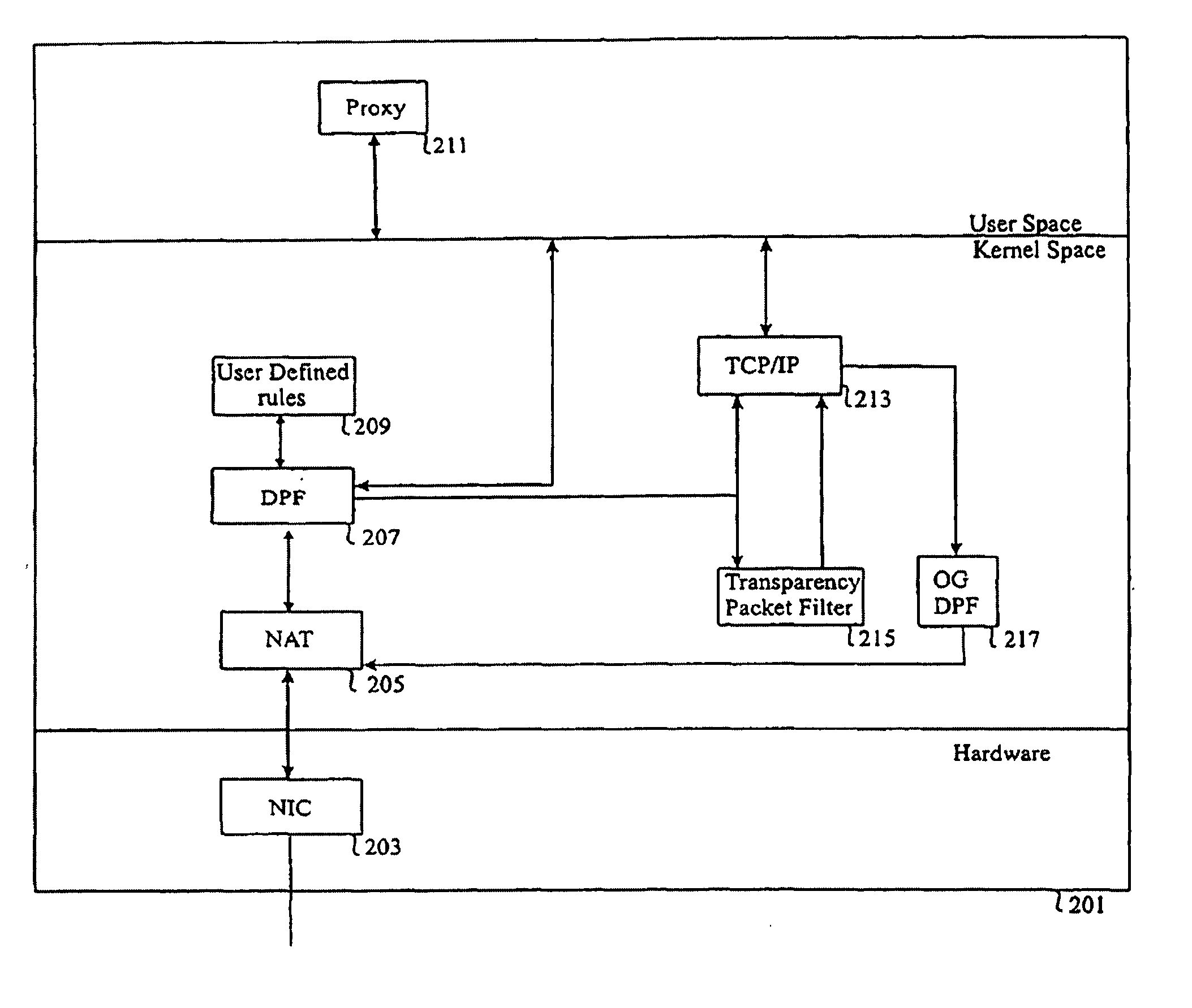
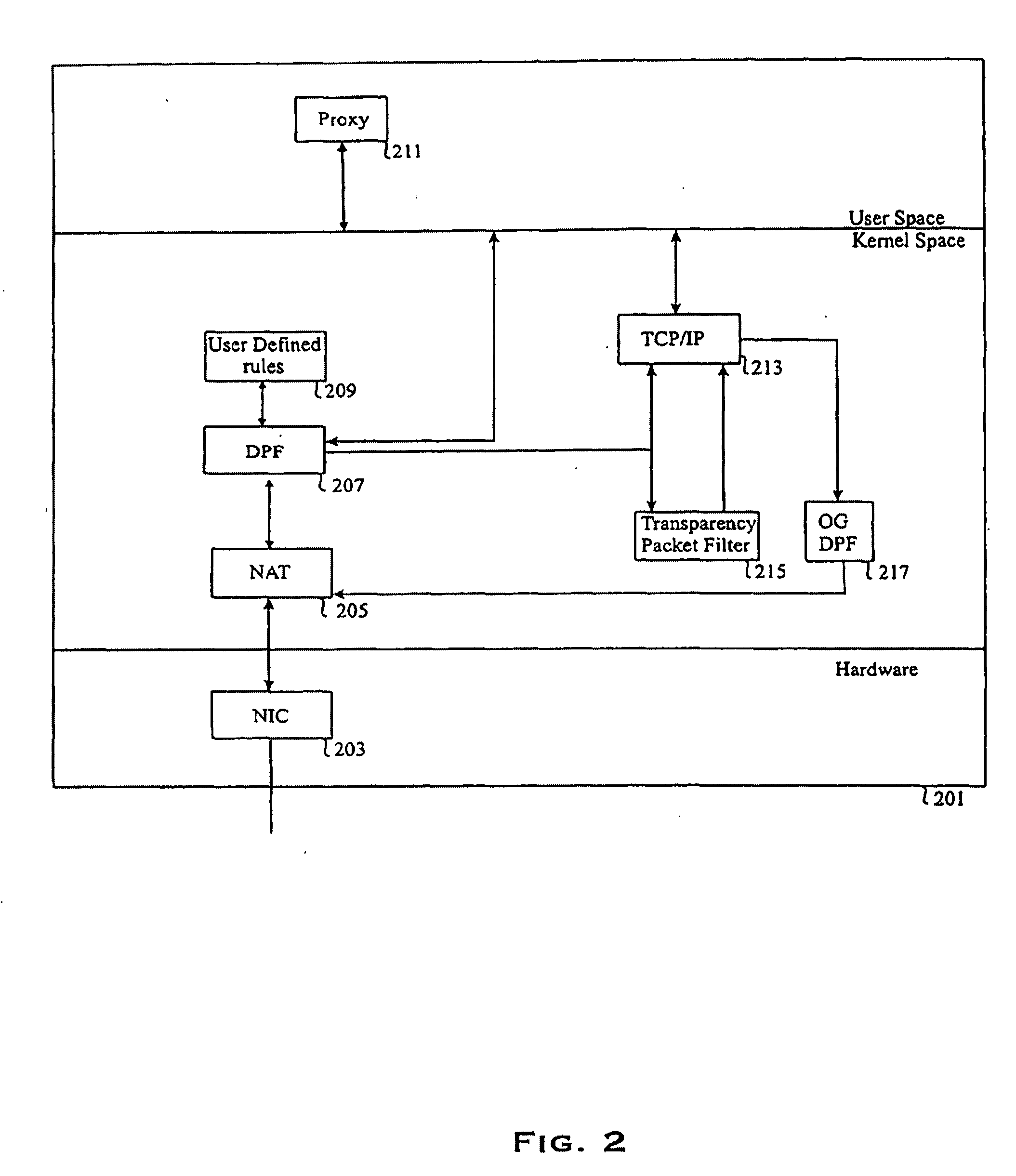
[0032]Referring to FIG. 2, there is illustrated an overall block diagram of a firewall 201 of the present invention that includes a Network Interface Card (NIC) 203 coupled to at least one outside network. NIC 203 is also coupled to a Network Address Translation module (NAT) 205 which in turn is coupled to a Dynamic Packet Filter module (DPF) 207. DPF 207 is coupled to a proxy 211, a User Defined Static Packet Filter module (UD-SPF) 209, Transparency Packet Filter (TPF) 215, and a local Transmission Control Protocol / Internet Protocol stack (TCP / IP) 213. TCP / IP 213 in turn is coupled to an Out-Going Dynamic Packet Filter (OG-DPF) 217.

[0033]It should also be noted that the term “coupled” should be interpreted to mean one of many connection methods. For instance, NIC 203 may be coupled to the at least one outside network via wire or wireless communication connections, whereas NIC 203 may be coupled to NAT via physical wires. However, when two coupled modules are implemented in computer...


PUM


Abstract

A method, system and computer program for providing multilevel security to a computer network. The method comprises the step of receiving a first communication packet on at least one network interface port from an outside network. The method further includes the steps of filtering the first packet in one of at least two levels of security comprising a first level of security which examines the content information of the packet and a second level of security which examines the first packet excluding the content information of the packet. The system includes a first packet filter configured to filter its input packets by examining content information of its packets and a second packet filter configured to filter its input packets by examining the header information without examining the content information of its packets. The system further includes a third filter which is configured to forward a number of packets to one of the first and second filters, thereby providing security to the computer network. The computer program includes a first module located in an application layer, a second module located in a network layer, and a third module located in a kernel space and configured to examine a number of packets received by the computer network from at least one outside network and to forward the number of packets to one of the first and second modules after examining the number of packets.

Description

RELATED APPLICATION(S)[0001]The present application is a continuation of a patent application filed Jan. 12, 2004 under Ser. No. 10 / 756,687 which is, in turn, a continuation of an application filed Oct. 8, 1999 under Ser. No. 09 / 414,711, now U.S. Pat. No. 6,728,885, which, in turn, claims the benefit of a provisional patent application filed Oct. 9, 1998 under Ser. No. 60 / 103,837, all of which are incorporated herein by reference.FIELD OF INVENTION[0002]This invention relates to providing security in communication networks. In particular, the invention relates to firewall technology in packet switched networks for adaptively providing a plurality of security levels.BACKGROUND OF THE INVENTION[0003]Referring to FIG. 1, a typical firewall 101 is placed between a Local Area Network (LAN) 103 and outside networks 111, 115. LAN 103 may include a plurality of internal hosts 105, 107, 109. Outside networks 111 can be networked through the Internet 117. Outside network 115 may also include ...

Claims


Application Information

Patent Timeline
Patent Type & Authority Applications(United States)
IPC IPC(8): H04L9/32G06F15/16H04L29/06
CPCH04L63/0263H04L63/0281H04L63/104
Inventor TAYLOR, KEVIN R.MURUGESAN, GANESHTAJALLI, HOMAYOON
Owner MCAFEE LLC
Why Eureka
Try Eureka