
Movable coil scanner systems and methods

a scanner and moving coil technology, applied in the direction of magnetic property measurement, instruments, material magnetic variables, etc., can solve the problems of not including a free space sensor or array, mri systems do not provide a direct magnetic field feedback mechanism,

Active Publication Date: 2013-09-26
TDK CORPARATION
View PDF27 Cites 1 Cited by
  • Summary
  • Abstract
  • Description
  • Claims
  • Application Information

AI Technical Summary

Benefits of technology

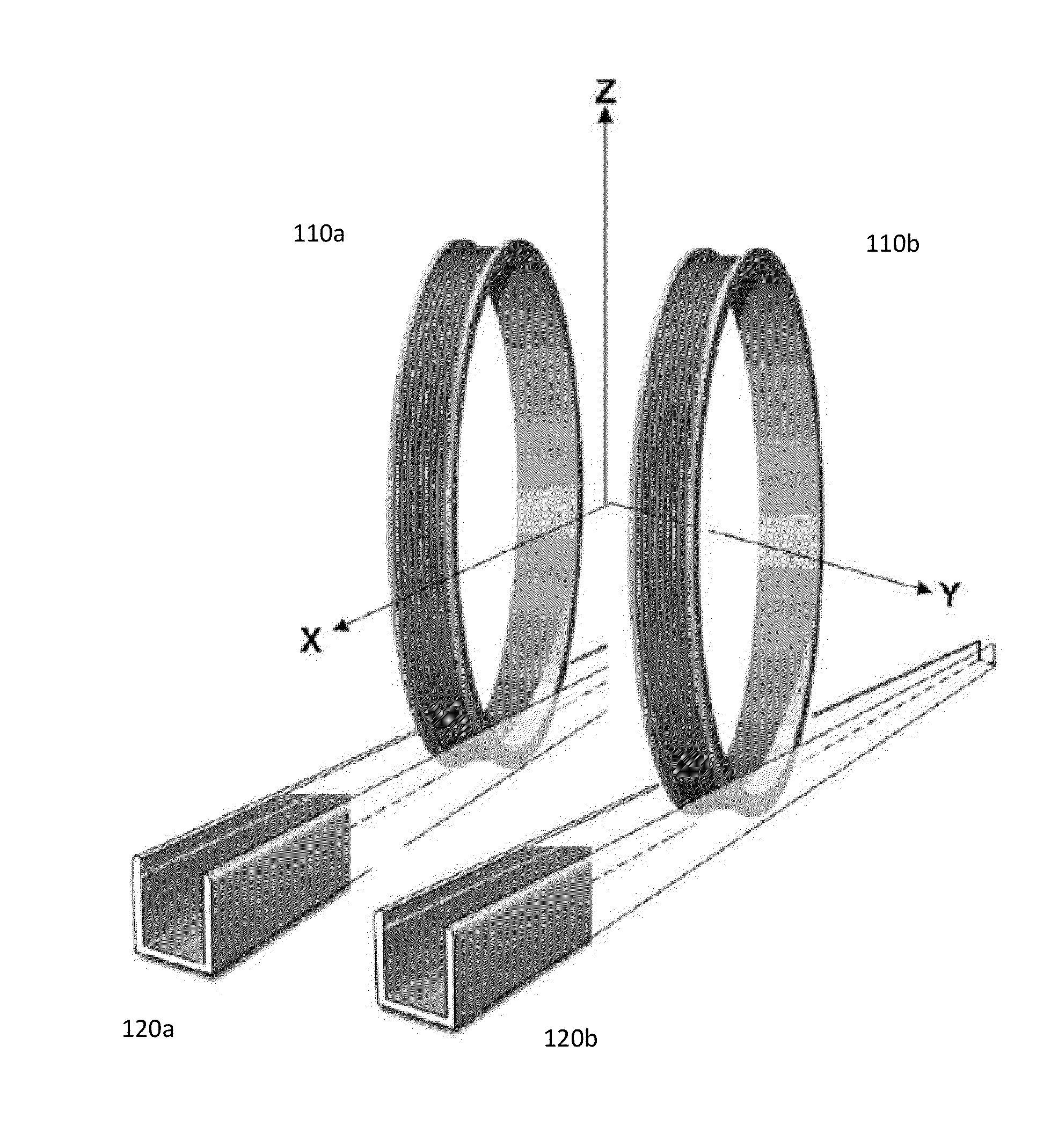
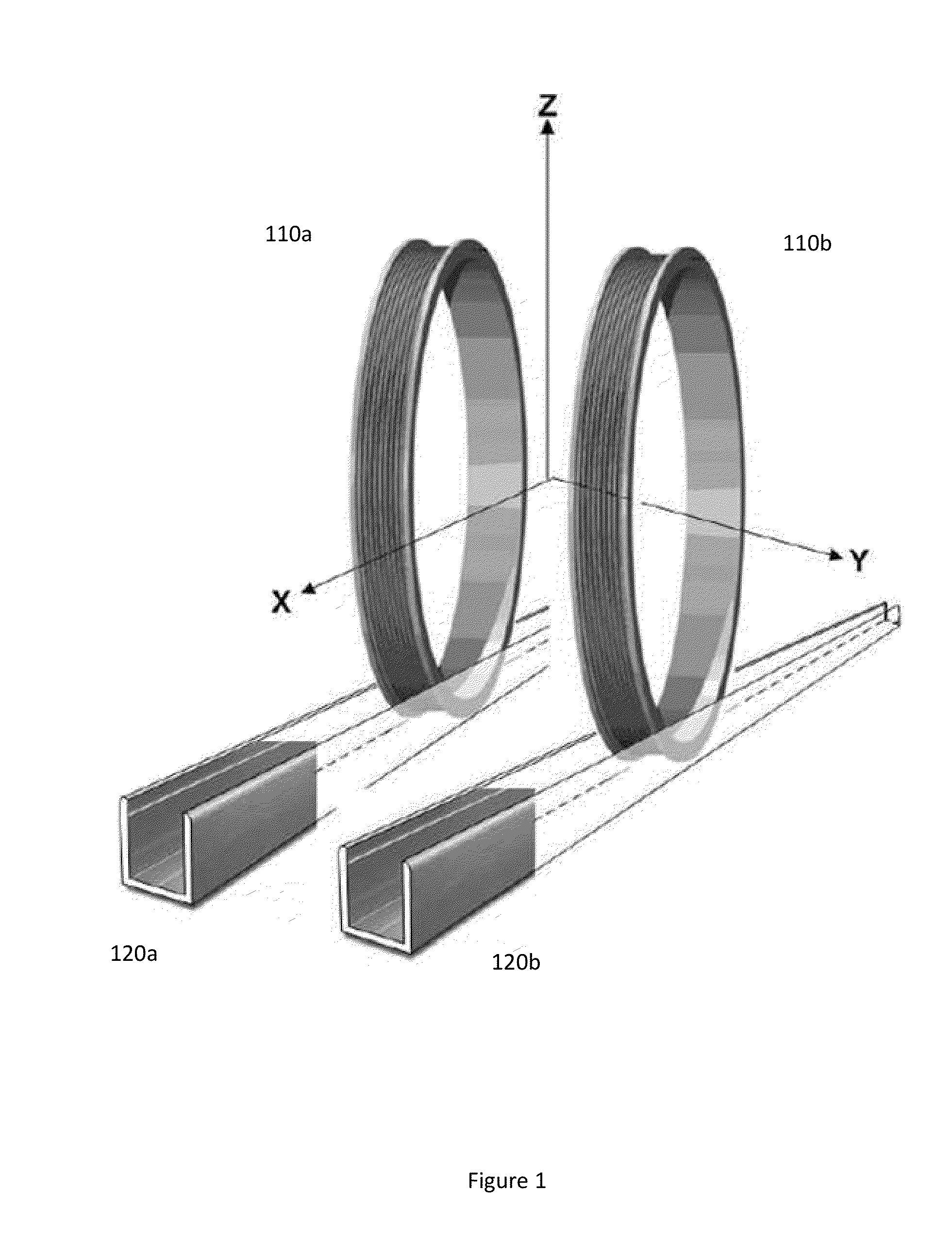
The patent describes a system for generating a controlled and calibrated magnetic field over a scanning volume for a vehicle. The system includes two coils that generate magnetic fields in opposite directions, with the fields combining to form a combined magnetic field. The system also includes transporters to move the coils in different directions. The combined magnetic field can be adjusted to scan the vehicle and create a calibrated magnetic field for accurate measurements. This system can provide a more efficient and precise tool for the analysis and testing of vehicles.

Problems solved by technology

Likewise, applications like MRI systems do not provide a direct magnetic field feedback mechanism.
Thus, MRI systems do not include a free space sensor or array of free space sensors placed within the test volume for magnetic field monitoring.

Method used


Image

  • Movable coil scanner systems and methods
  • Movable coil scanner systems and methods
  • Movable coil scanner systems and methods

Examples

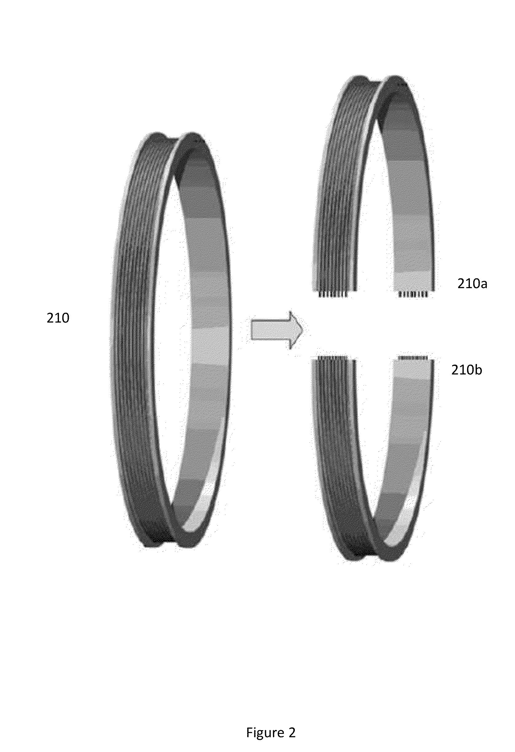

Embodiment Construction

[0026]Certain embodiments relate to a coil scanning system that can be used to generate a controlled and calibrated magnetic field over a large prescribed test volume. Certain embodiments, therefore, employ precision location and control of an array of field generating coils.

[0027]Certain embodiments can apply to volumes that are significantly larger than volumes addressed by MRI or calibration equipment. For example, certain embodiments may scan the volume of a motorcycle, a car, or a truck. For example, certain embodiments may have a scanning volume of 50 cubic feet to 5000 cubic feet, and more particularly from 100 cubic feet to 1000 cubic feet. Any volume suitable for a tested vehicle, however, may be accommodated by certain embodiments.

[0028]Fixed-coil configurations, such as the Helmholtz geometries, are not required in certain embodiments. Instead, mobile coil geometries in one or all dimensions can be employed. This may allow different field volumes to be addressed. Addition...


PUM


Abstract

A system, such as a magnetic immunity testing system, can include a first coil configured to generate a first magnetic field. The first coil can be disposed on a first side of a scanning volume and can have a first feed for supplying electric current to the first coil. A second coil can be similarly configured on an opposite side of a scanning volume, and a second magnetic field from the second coil can be combined with the first magnetic field to form a combined magnetic field. The coils can be provided with transporters that translate coils in at least one dimension. The system can also include a controller that is configured to control the transporters and the feeds to provide the combined magnetic field as a controlled and calibrated magnetic field over the scanning volume.

Description

CROSS REFERENCE TO RELATED APPLICATION[0001]This application is related to and claims the priority of U.S. Provisional Patent Application No. 61 / 614,330, filed Mar. 22, 2012, which is hereby incorporated herein by reference in its entirety.BACKGROUND[0002]1. Field[0003]Movable coil scanner systems and methods may be beneficial to a variety of testing environments and processes. For example, testing of vehicles such as automobiles may benefit from movable coil scanner systems that are configured to perform magnetic immunity testing.[0004]2. Description of the Related Art[0005]Conventional magnetic field generation and multi-coil use is mainly in two areas. A first area is calibration. In this area, coil configurations of specific geometries, for example, Helmholtz geometries, can be used to generate well behaved and predictable magnetic fields that can be used to calibrate magnetic field probes.[0006]A second area is magnetic resonance imaging (MRI). In this area, coil configurations...

Claims


Application Information

Patent Timeline
Patent Type & Authority Applications(United States)
IPC IPC(8): G01R33/12
CPCG01R31/001G01R33/12G01R31/006
Inventor SUTTON, ROBERT
Owner TDK CORPARATION
Learn More