Input device

a technology of input device and signal line, which is applied in the direction of electronic switching, pulse technique, instruments, etc., can solve the problems of button operation unintended by users, unintended user operation, and reduced signal line complexity, so as to reduce the number of signal lines

Active Publication Date: 2013-09-26
BROTHER KOGYO KK
View PDF4 Cites 3 Cited by
  • Summary
  • Abstract
  • Description
  • Claims
  • Application Information

AI Technical Summary

Benefits of technology

[0007]The above-described input device can reduce the number of signal lines by utilizing the combination of the first electrode and the second electrode to perform the button operation. However, the reduction in the number of signal lines also reduces the number of combinations of the first electrode and the second electrode, leading to a button operation unintended by a user. Specifically, in a case where an input object approaches a position between two adjacent input buttons, it may be determined that one of the two input buttons has been operated. This erroneous operation is caused in a case where, as will be explained later in detail, a combination of a first electrode and a second electrode on one input button is the same as a combination of the first electrode on the one button and a second electrode on a button adjacent to the one button, for example.

Problems solved by technology

However, since complexity of routing increases with increase in the number of signal lines, the number of signal lines is preferably small.
However, the reduction in the number of signal lines also reduces the number of combinations of the first electrode and the second electrode, leading to a button operation unintended by a user.

Method used


Image

  • Input device
  • Input device
  • Input device

Examples


first embodiment

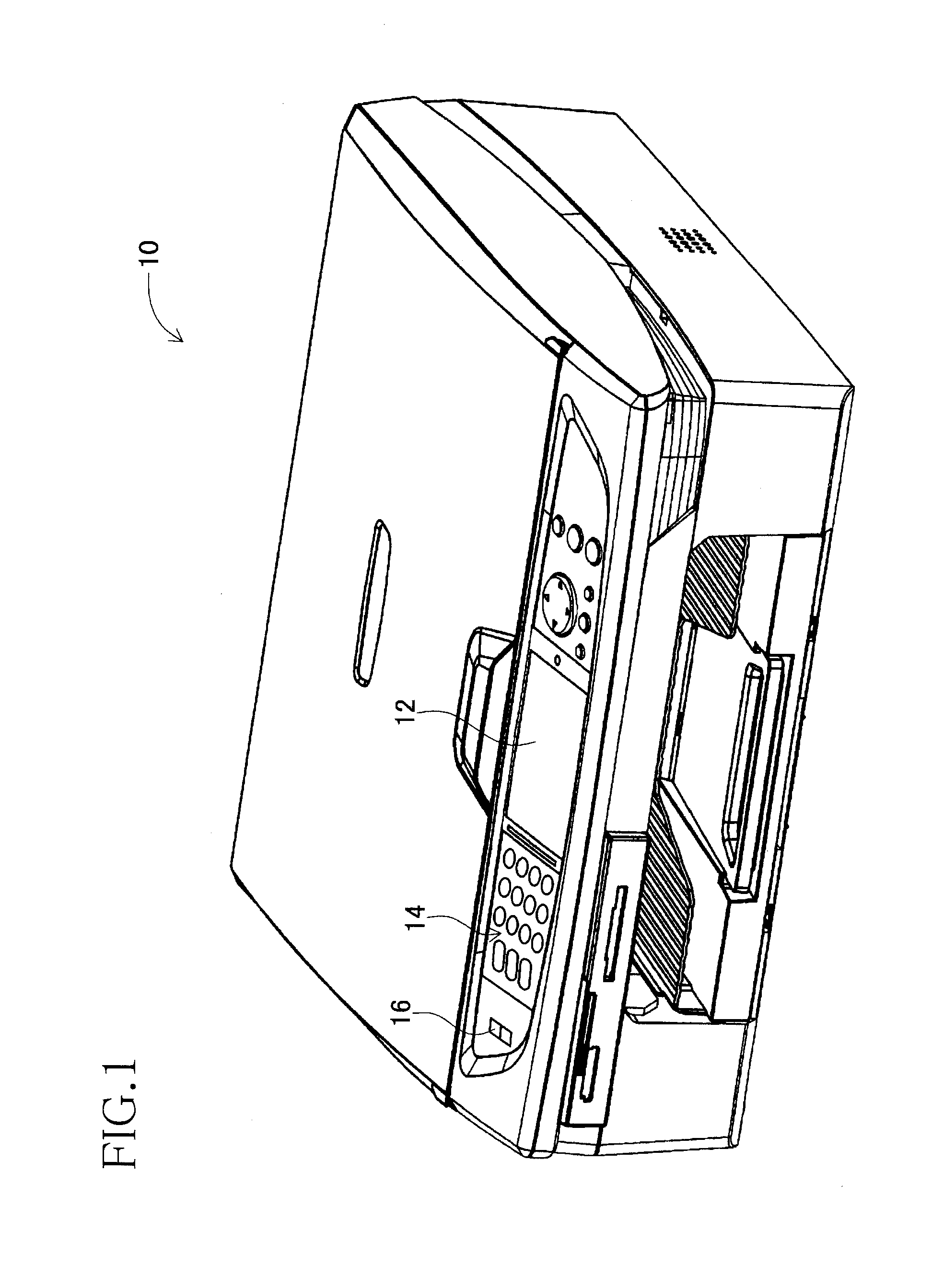
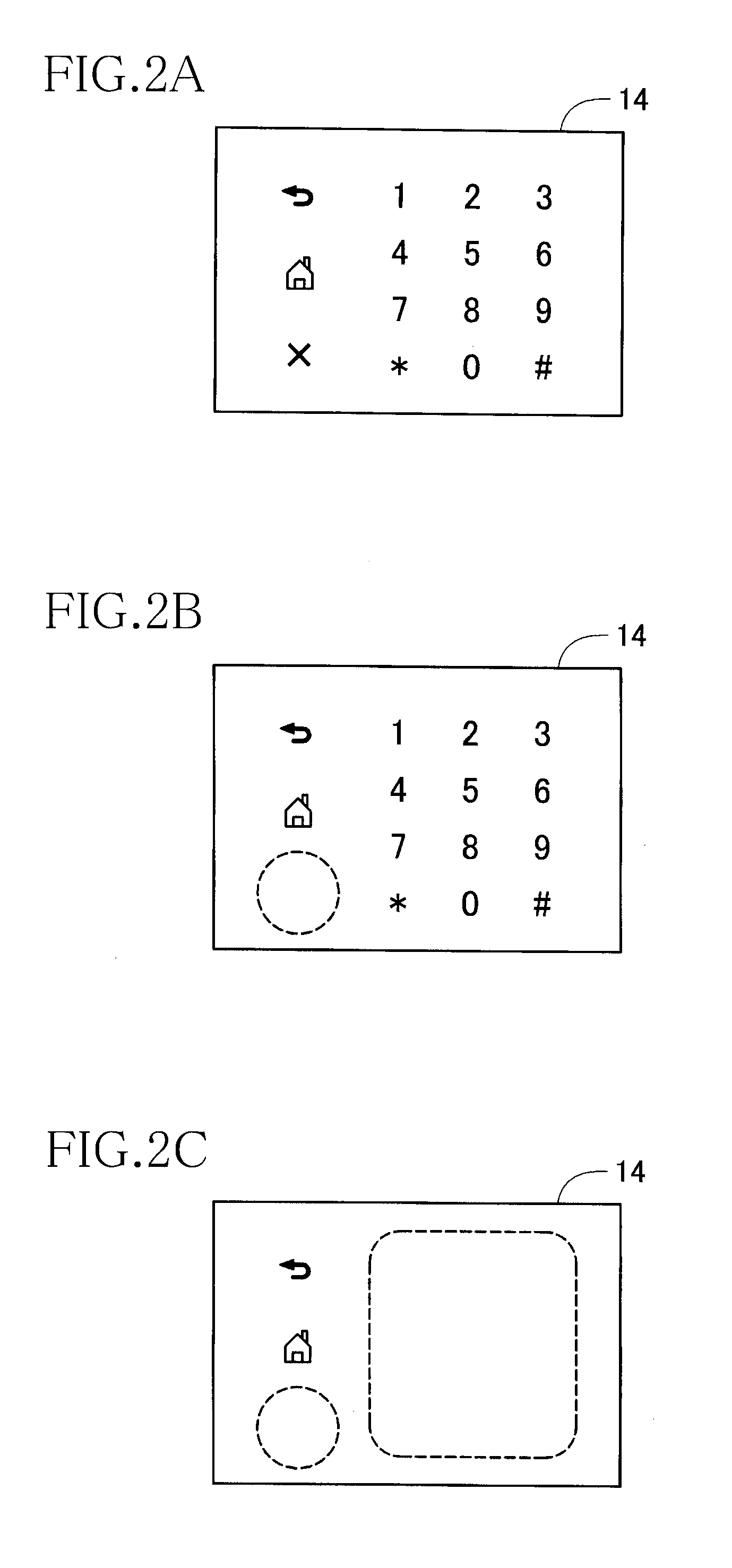
[0026]FIG. 1 illustrates a multi-function peripheral (MFP) according to a first embodiment of the present invention. This MFP 10 has various functions such as a facsimile function, a printing function, a scanning function, and a copying function. Provided on a front central portion of an upper face of the MFP 10 is a display panel 12 for displaying various information of the functions of the MFP 10. A touch panel 14 is provided on a left side of the display panel 12. The MFP 10 performs various operations in response to a user's input on the touch panel 14. Also, a mechanical main power switch 16 is provided on a left side of the touch panel 14.

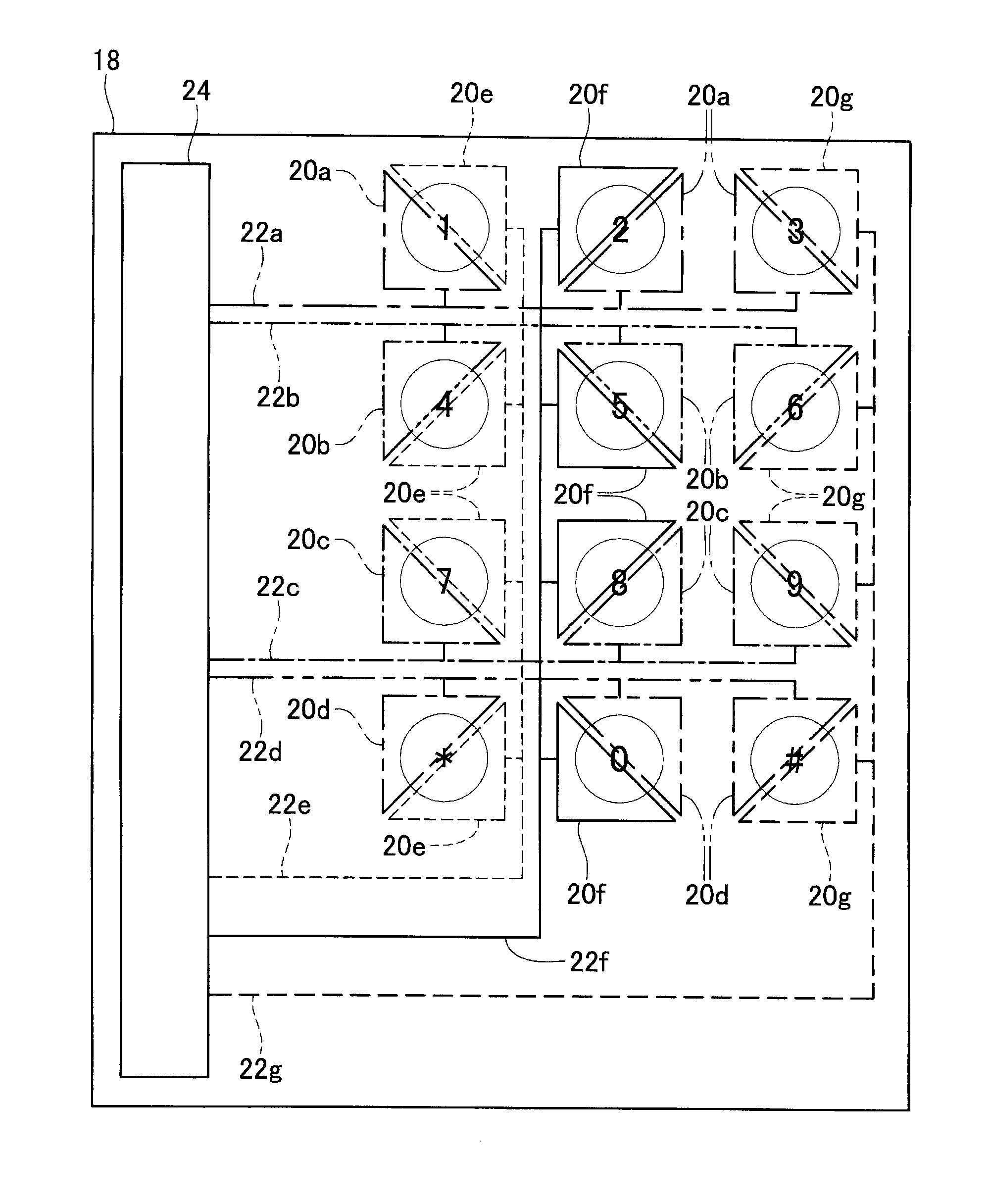
[0027]The touch panel 14 is an electrostatic capacitance touch panel that includes: a board or a substrate 18 (see FIG. 3) on which the plurality of electrodes are arranged; and a transparent top coat covering the board 18. Signs such as numbers are described on the top coat, and the electrodes are arranged at positions respectively opposed t...

second embodiment

[0081]There will be next explained a board 50 in a second embodiment with reference to FIG. 9. Since the board 50 in the second embodiment has a structure similar to that of the board 30 as the comparative example except for its connection pattern, the same reference numerals as used in the comparative example are used to designate the corresponding elements in this second embodiment, and an explanation of which is omitted or simply given.

[0082]Also in this board 50 in the second embodiment, the signal lines 22 and electrodes 52 are connected to one another in the connection pattern similar to that of the board 18 in the first embodiment. There will be explained, by way of specific example, a signal line 22a corresponding to the touch areas arranged in the uppermost row. The signal line 22a is connected to: an electrode 52a disposed on a lower left portion of the touch area “1”; an electrode 52a disposed on an upper right portion of the touch area “2”; and an electrode 52a disposed ...

third embodiment

[0087]There will be next explained a board 60 in a third embodiment with reference to FIG. 10. Since the board 60 in the third embodiment has a structure similar to that of the board 18 in the first embodiment except for its connection pattern and the shape of the electrodes, the same reference numerals as used in the first embodiment are used to designate the corresponding elements in this third embodiment, and an explanation of which is omitted or simply given.

[0088]In the board 60 in the third embodiment, one touch area is formed by two electrodes 62 each having a right triangle shape and one electrode 62 having an isosceles triangle shape. Specifically, three electrodes 62 are arranged in a state in which a hypotenuse of one of the two right-triangle shaped electrodes 62 faces one of equal-length legs of the isosceles-triangle shaped electrode 62, and the other of the equal-length legs of the isosceles-triangle shaped electrode 62 faces a hypotenuse of the other of the two right...


PUM


Abstract

An input device includes a first input detector and a second input detector adjacent to each other. The first input detector includes: a first electrode unit coupled to a first signal line; and a second electrode unit coupled to a second signal line. The second input detector includes: a first electrode unit coupled to the first signal line; and a third electrode unit coupled to a third signal line. The first input detector and the second input detector are arranged in one of a state in which the first electrode unit of the first input detector and the first electrode unit of the second input detector are adjacent to each other and a state in which the second electrode unit of the first input detector and the third electrode unit of the second input detector are adjacent to each other.

Description

CROSS REFERENCE TO RELATED APPLICATION[0001]The present application claims priority from Japanese Patent Application No. 2012-069798, which was filed on Mar. 26, 2012, the disclosure of which is herein incorporated by reference in its entirety.BACKGROUND[0002]1. Field of the Invention[0003]The present invention relates to an input device provided with a plurality of input buttons.[0004]2. Description of the Related Art[0005]Examples of an input device provided with a plurality of input buttons include an electrostatic capacitance touch panel. The electrostatic capacitance touch panel is designed to perform a button operation by utilizing a change in an electrostatic capacity caused when an input object contacts or approaches an input button. In such a touch panel, one or more electrodes are provided for each input button. Each electrode is connected to a corresponding one of signal lines each for outputting an output value, so that an increase in the number of input buttons tends to...

Claims


Application Information

Patent Timeline
Patent Type & Authority Applications(United States)
IPC IPC(8): G06F3/041
CPCG06F3/0418H03K2017/9613H03K17/9622G06F2203/04108G06F3/02
Inventor AKAGI, KOJI
Owner BROTHER KOGYO KK
Why Eureka
Try Eureka