Electromagnetic Driving Device for Lens having an Anti-Tilt Mechanism
a driving device and anti-tilt technology, applied in the direction of mountings, optics, instruments, etc., can solve the problems of high cost, substantial occupation, and difficult assembly, and achieve the effect of reducing the spacing variance caused by the surface unevenness of the guide mechanism between the lens carrier and the casing, preventing the possibility of tilting of the driven parts, and ensuring the straightness of the moving lens and the perpendicularity of the photo axis
- Summary
- Abstract
- Description
- Claims
- Application Information
AI Technical Summary
Benefits of technology
Problems solved by technology
Method used
Image
Examples
first embodiment
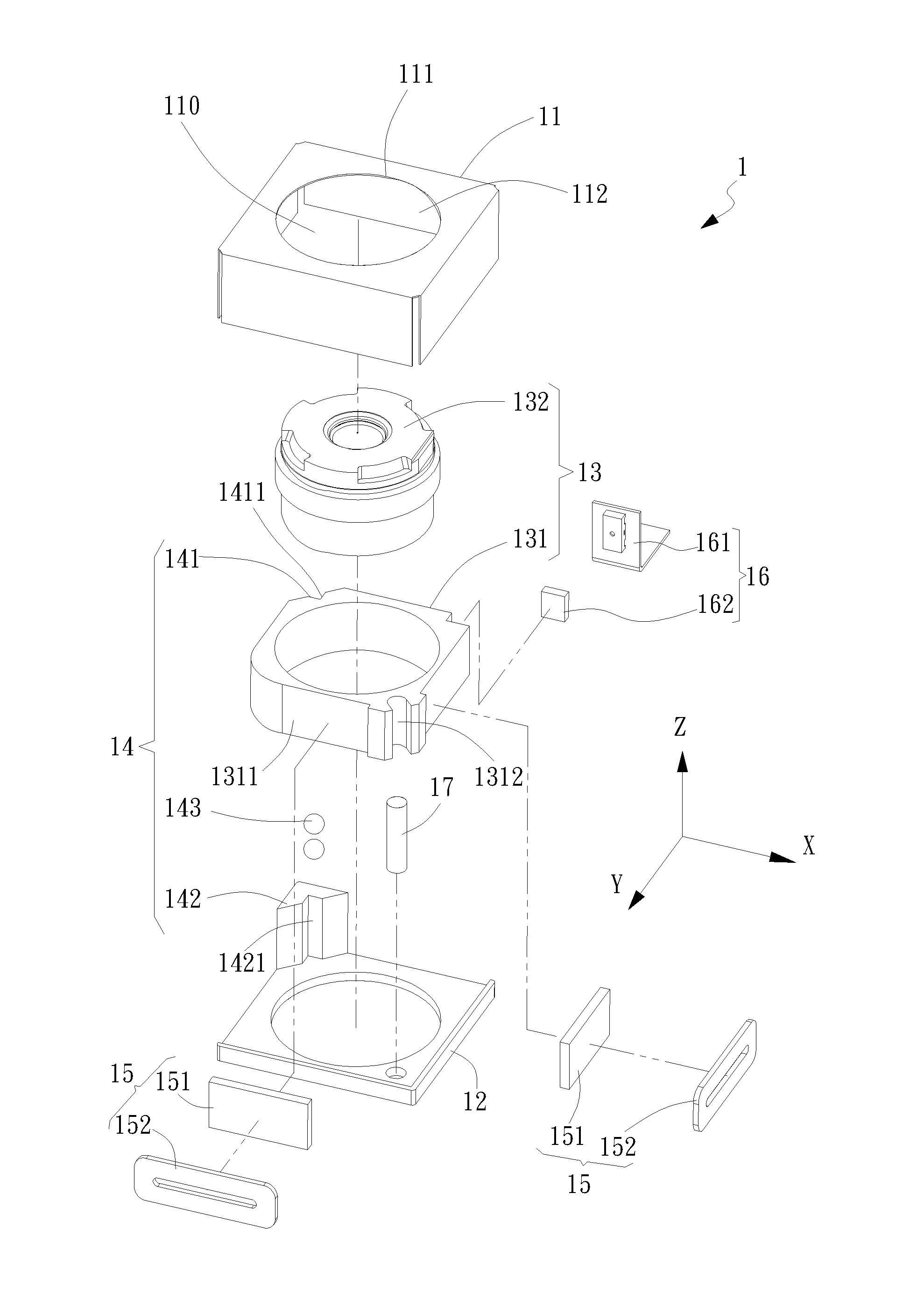
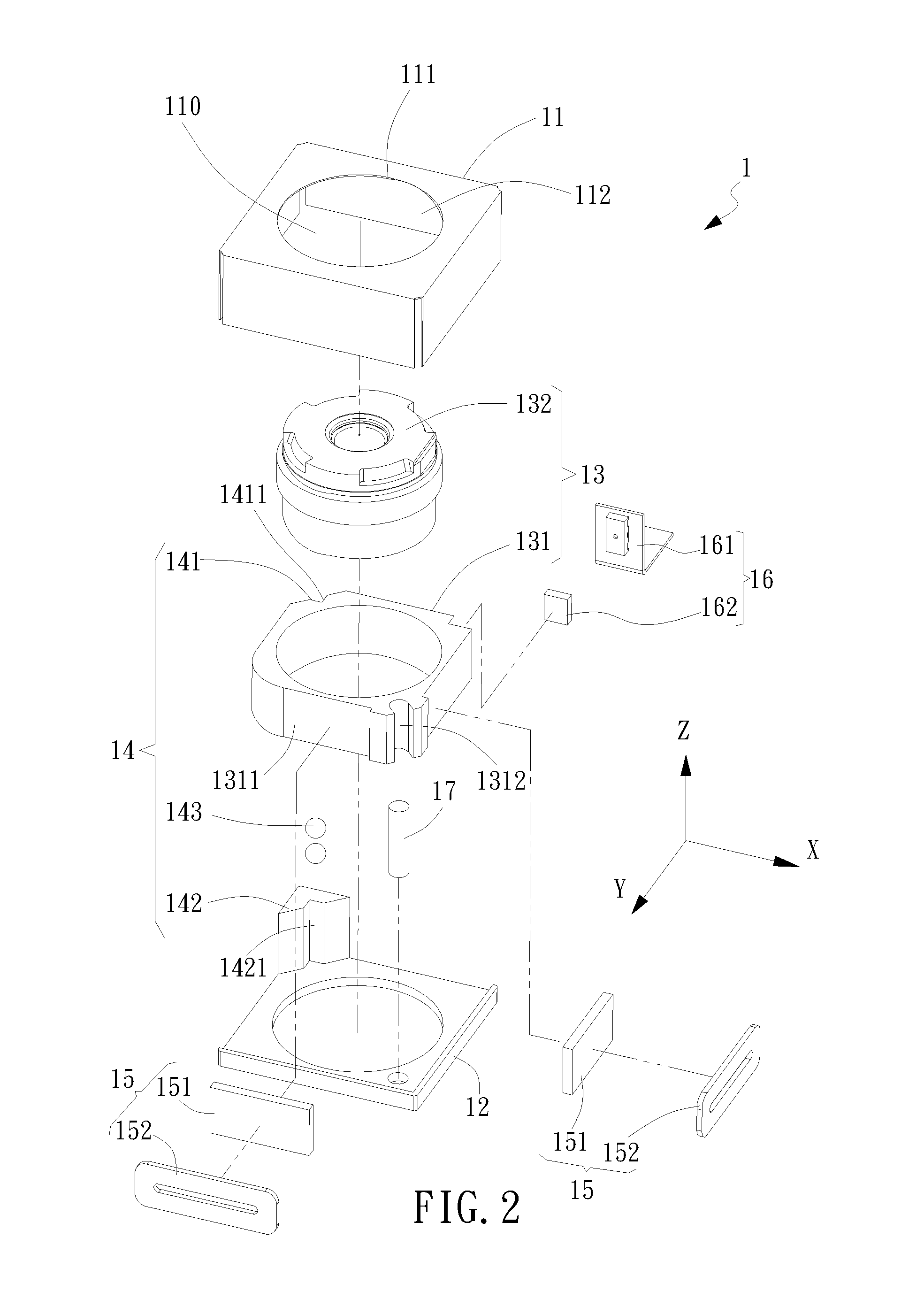
[0035]Referring now to FIG. 2, FIG. 3, FIG. 4, FIG. 5, FIG. 6 and FIG. 7, an exploded view, a top view, a left-hand side view, a cross-sectional view along line A-A, a cross-sectional view along line B-B and a cross-sectional view along line C-C of the electromagnetic driving device 1 for lens having an anti-tilt mechanism are shown, respectively. The electromagnetic driving device 1 defined with an X axis, a Y axis and a Z axis includes a casing 11, a base 12, a driven object 13, an anti-tilt mechanism 14, an electromagnetic driving module 15, a position-detecting module 16 and a guide mechanism 17. The casing 11 connects to the base 12 so as to form an inner compartment 110 therein. The driven object 13 inside the compartment 110 is received and movable along the Z axis.
[0036]In the first embodiment as shown, the driven object 13 can be a lens module. The lens module 13 further includes a lens carrier 131 and a lens 132. The lens 132 located at a center of the lens carrier 131 is ...
second embodiment
[0052]Further, in the second embodiment la, the second constraint block 144a is located laterally to the U-shape contact surface 1461a of the third guide-groove 146a so as to serve a fixation purpose for the preset spring member 148a, and the second constraint block 144a can elastically force the rolling member 143 onto the U-shape contact surface 1461a via the elastic end 1482a of the preset spring member 148a and also further presses, in an indirect way across the lens carrier 131a, the opposing rolling member 143 onto the second constraint block 145a. Upon such an arrangement, in the inner compartment 110, the lens module 13a can be hold with a controllable loading onto the guide rack mechanism formed by the constraint block 142a and the third constraint block 145a. Namely, the contact states, not the fixation states, prevail in the lens module 13a among the lens carrier 131a, the rolling member 143 and the preset spring member 148a. In particular, besides pre-forcing the rolling...
PUM
 Abstract
Description
Claims
Application Information
 - R&D
- Intellectual Property
- Life Sciences
- Materials
- Tech Scout
- Unparalleled Data Quality
- Higher Quality Content
- 60% Fewer Hallucinations
Browse by: Latest US Patents, China's latest patents, Technical Efficacy Thesaurus, Application Domain, Technology Topic, Popular Technical Reports.
© 2025 PatSnap. All rights reserved.Legal|Privacy policy|Modern Slavery Act Transparency Statement|Sitemap|About US| Contact US: help@patsnap.com


