capillary heat exchanger

A capillary tube and heat exchanger technology, which is applied in indirect heat exchangers, heat exchanger types, fixed conduit components, etc., can solve the problems of low utilization rate of refrigerant and reduced heat exchange efficiency of heat exchangers, so as to reduce production costs, The effect of uniform pipe spacing and avoiding bending deformation

Active Publication Date: 2021-07-20
ZHEJIANG DUNAN MASCH CO LTD
View PDF10 Cites 0 Cited by
  • Summary
  • Abstract
  • Description
  • Claims
  • Application Information

AI Technical Summary

Problems solved by technology

[0003] The purpose of the present invention is to provide a capillary heat exchanger to solve the problems in the prior art that the heat exchange efficiency of the heat exchanger is reduced and the refrigerant utilization rate is low due to the excessively large diameter of the heat exchange tube.

Method used


Image

  • capillary heat exchanger
  • capillary heat exchanger
  • capillary heat exchanger

Examples


Embodiment Construction

[0022] Embodiments of the invention are described in detail below, but the invention can be practiced in many different ways as defined and covered by the claims.

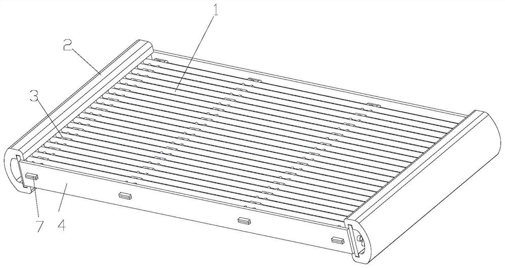
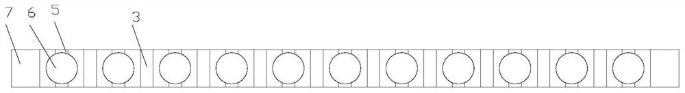
[0023] Please refer to Figure 1 to Figure 3 As shown, according to the first embodiment of the present invention, the capillary heat exchanger includes multiple rows of capillary tubes 1 and headers 2 located at both ends of the capillary tubes 1, each row of capillary tubes 1 includes a plurality of capillary tubes 1 arranged at intervals, and each row of capillary tubes 1 The space is supported and fixed by a support block 3, which extends along the arrangement direction of each row of capillary tubes 1, and the two ends of the support block 3 are fixed by side plates 4 arranged on the header 2.

[0024] Preferably, the top and bottom of the support block 3 are provided with semicircular support grooves 5 matching with the capillary 1, and the semicircular support grooves 5 of two adjacent support blocks 3 are c...


PUM


Abstract

The invention provides a capillary heat exchanger. The capillary heat exchanger includes multiple rows of capillary tubes (1) and headers (2) located at both ends of the capillary tubes (1), each row of capillary tubes (1) includes a plurality of capillary tubes (1) arranged at intervals, each row of capillary tubes (1) The support blocks (3) between them are supported and fixed, and the support blocks (3) extend along the arrangement direction of each row of capillary tubes (1), and the two ends of the support blocks (3) pass through the side plates arranged on the headers (2) (4) Fixed. According to the capillary heat exchanger of the present invention, the problems in the prior art that the heat exchange efficiency of the heat exchanger is reduced and the utilization rate of the refrigerant is low caused by the excessively large diameter of the heat exchange tube can be solved.

Description

technical field [0001] The invention relates to the technical field of heat exchangers, in particular to a capillary heat exchanger. Background technique [0002] The traditional tube-fin heat exchanger includes heat exchange tubes, fins, and headers located at both ends of the heat exchange tubes. Multiple heat exchange tubes are arranged in parallel, and the two ends of each heat exchange tube are respectively connected to the collectors at both ends. On the flow tubes, the heat exchange tubes are installed on the fins, and the heat dissipation area is increased through the fins to improve the heat exchange efficiency of the tube-fin heat exchanger. However, the diameter of the heat exchange tubes of the tube-fin heat exchanger is relatively large, which is not only high in cost, but also takes up a large volume, and the refrigerant located in the middle of the heat exchange tubes of the tube-fin heat exchanger is far away from the edge of the heat exchange tubes. Heat ex...

Claims


Application Information

Patent Timeline
Patent Type & Authority Patents(China)
IPC IPC(8): F28D1/047
CPCF28D1/0477
Inventor 汪峰尹逊同王东
Owner ZHEJIANG DUNAN MASCH CO LTD
Why Eureka
Try Eureka