Electromagnetic driving device for lens having an anti-tilt mechanism

a driving device and anti-tilt technology, applied in the direction of mountings, optics, instruments, etc., can solve the problems of high cost, substantial occupation, and difficult assembly, and achieve the effect of reducing the spacing variance caused by the surface unevenness of the guide mechanism between the lens carrier and the casing, preventing the possibility of tilting of the driven parts, and ensuring the straightness of the moving lens and the perpendicularity of the photo axis

Active Publication Date: 2014-09-09
TDK TAIWAN
View PDF1 Cites 5 Cited by
  • Summary
  • Abstract
  • Description
  • Claims
  • Application Information

AI Technical Summary

Benefits of technology

[0010]Accordingly, it is the primary object of the present invention to provide an electromagnetic driving device for lens having an anti-tilt mechanism, in which the anti-tilt mechanism is used to further cancel off possible tilt of the driven parts during the movement. Thereby, spacing variance caused by the surface unevenness of the guide mechanism between the lens carrier and the casing can be substantially reduced, the straightness of the moving lens as well as the perpendicularity of the photo axial can be assured, the stability in displacement control can be increased, and also precision positioning for the moving lens can be achieved.
[0012]The base connects to the casing so as to form an inner compartment therein. The driven object is received and movable along the Z axis inside the compartment. The anti-tilt mechanism is to provide a lateral horizontal push or pull on an X-Y surface to the driven object so as to restrain the horizontal or rotational movement of the driven object, and thereby the X-axial and / or Y-axial gap or spacing around the driven object inside the compartment can be eliminated. The magnetic member is fixed to the driven object and can be driven by magnetic forces generated by the coil which is fixed to the casing at a location corresponding to the magnetic member. By a predetermined sideward force provided by the anti-tilt mechanism, possible tilt caused by the gap or spacing between the driven object and the casing when the driven object is driven to move along the Z axis inside the compartment will be eliminated.

Problems solved by technology

Obvious disadvantages of such a mechanism 9 can be seen and well known in complicated structuring, tedious and difficult assembling, substantial occupation and high cost.
Also, the mechanism 9 consumes a lot of energy during the operation.
Such a human-dependent art causes problems for green hands.
In particular, while in a historical and un-repeated scene, a good timing for photography is usually missed for those ill-experienced photographers.
It is clear that, in the era of having the camera as one of popular 3C products for ordinary amateur people, the cumbersome zooming lens module driven mechanically by the step-motor is now an obstacle for further miniaturizing the camera products.
Nevertheless, operations of all the above-mentioned portable products are limited to their own battery capacities.
However, such spacing lead to a tilt problem for the lens module, both in movement and in stops.

Method used


Image

  • Electromagnetic driving device for lens having an anti-tilt mechanism
  • Electromagnetic driving device for lens having an anti-tilt mechanism
  • Electromagnetic driving device for lens having an anti-tilt mechanism

Examples


first embodiment

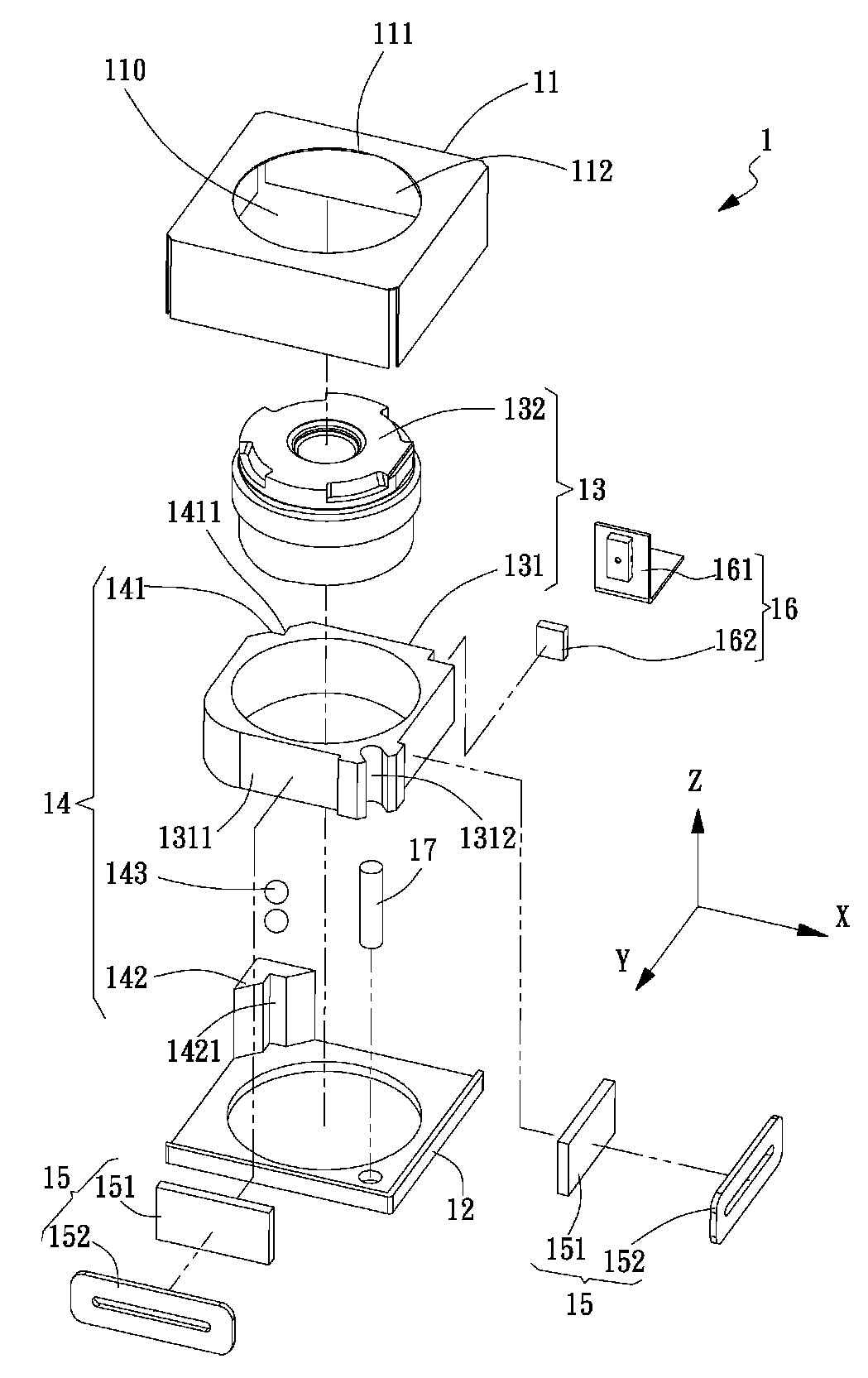
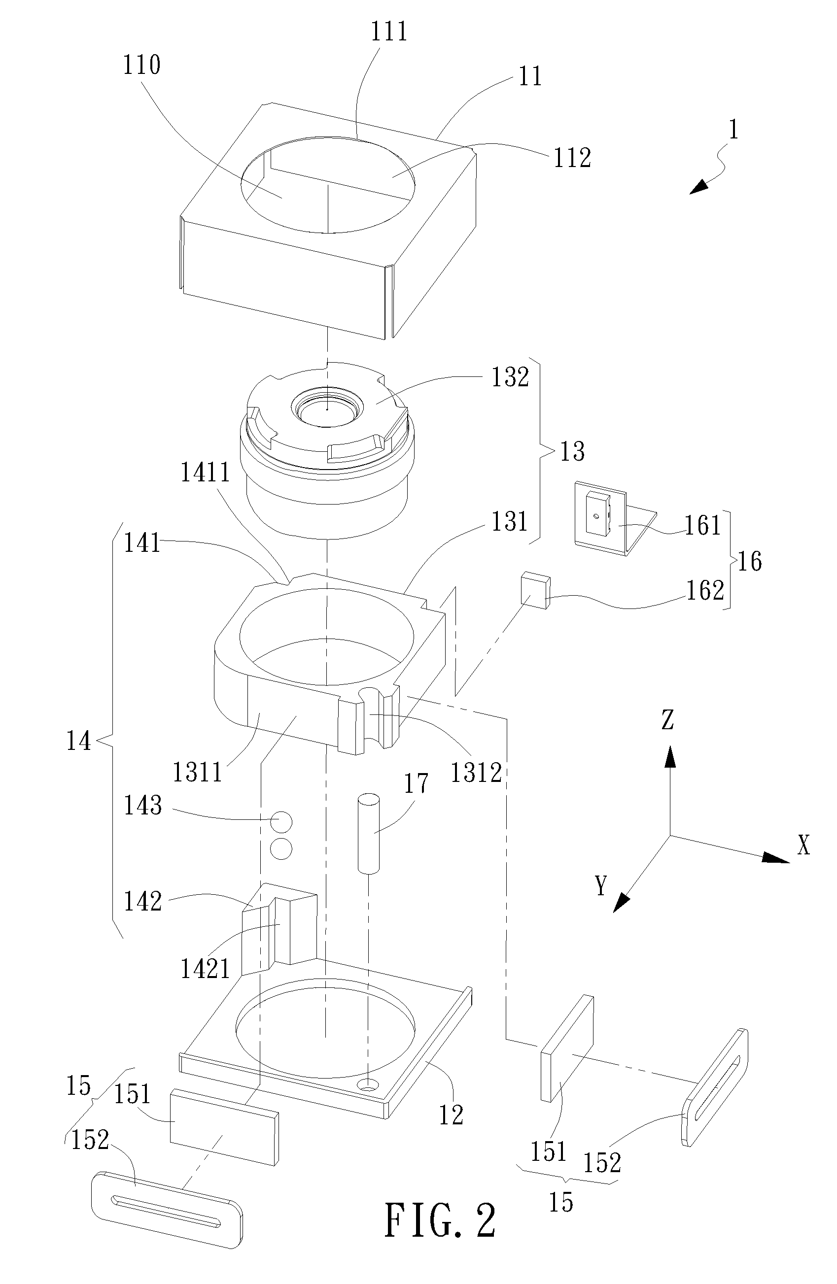
[0035]Referring now to FIG. 2, FIG. 3, FIG. 4, FIG. 5, FIG. 6 and FIG. 7, an exploded view, a top view, a left-hand side view, a cross-sectional view along line A-A, a cross-sectional view along line B-B and a cross-sectional view along line C-C of the electromagnetic driving device 1 for lens having an anti-tilt mechanism are shown, respectively. The electromagnetic driving device 1 defined with an X axis, a Y axis and a Z axis includes a casing 11, a base 12, a driven object 13, an anti-tilt mechanism 14, an electromagnetic driving module 15, a position-detecting module 16 and a guide mechanism 17. The casing 11 connects to the base 12 so as to form an inner compartment 110 therein. The driven object 13 inside the compartment 110 is received and movable along the Z axis.

[0036]In the first embodiment as shown, the driven object 13 can be a lens module. The lens module 13 further includes a lens carrier 131 and a lens 132. The lens 132 located at a center of the lens carrier 131 is ...

second embodiment

[0052]Further, in the second embodiment la, the second constraint block 144a is located laterally to the U-shape contact surface 1461a of the third guide-groove 146a so as to serve a fixation purpose for the preset spring member 148a, and the second constraint block 144a can elastically force the rolling member 143 onto the U-shape contact surface 1461a via the elastic end 1482a of the preset spring member 148a and also further presses, in an indirect way across the lens carrier 131a, the opposing rolling member 143 onto the second constraint block 145a. Upon such an arrangement, in the inner compartment 110, the lens module 13a can be hold with a controllable loading onto the guide rack mechanism formed by the constraint block 142a and the third constraint block 145a. Namely, the contact states, not the fixation states, prevail in the lens module 13a among the lens carrier 131a, the rolling member 143 and the preset spring member 148a. In particular, besides pre-forcing the rolling...


PUM


Abstract

An electromagnetic driving device defined with an X axis, a Y axis and a Z axis includes a casing, a base, a driven object, an anti-tilt mechanism and an electromagnetic driving module. The electromagnetic driving module includes at least one magnetic member and at least one coil. The base connects to the casing so as to form an inner compartment thereinside. The driven object is received and movable along the Z axis inside the inner compartment. The magnetic member fixed to the driven object can be driven by magnetic forcing generated by the respective coil fixed to the casing. With the anti-tilt mechanism to provide lateral pressing forcing to eliminate possible gap between components connecting the driven object and the casing while the driven object is moved along the Z axis inside the inner compartment, possible dynamic tilt of the moving driven object can then be diminished.

Description

BACKGROUND OF INVENTION[0001]1. Field of the Invention[0002]The invention relates to an electromagnetic driving device for lens having an anti-tilt mechanism, in which the anti-tilt mechanism can correct possible sideward tilt of the lens while in operation so as to stabilize a smooth movement of the lens.[0003]2. Description of the Prior Art[0004]Please refer to FIG. 1, in which a conventional zooming or focusing lens module is explodedly shown. In this conventional design, a mechanical transmission zooming mechanism 9 is utilized. The mechanism 9 uses a high-cost precision driving element 91 as its source power for a carrier 93 of the lens module 92 and a lot more transmission elements are involved in the mechanism 9. In the art, the aforesaid high-cost precision driving element 91 can be a step motor, a supersonic motor, a piezoelectric actuator, and so on. Obvious disadvantages of such a mechanism 9 can be seen and well known in complicated structuring, tedious and difficult ass...

Claims


Application Information

Patent Timeline
Patent Type & Authority Patents(United States)
IPC IPC(8): G02B7/02
CPCG02B7/08
Inventor LEE, JIN, YU
Owner TDK TAIWAN
Why Eureka
Try Eureka