Connector connecting bolt, connector and connector assembly

a technology of connecting bolts and connectors, applied in the direction of connection of coupling devices, washers, ways, etc., can solve the problems of affecting the sealing groove, unable to enter the seal groove, interfering with the flange, etc., and achieve the effect of preventing damage to the surface of the sealing groov

Active Publication Date: 2013-10-03
SUMITOMO WIRING SYST LTD
View PDF11 Cites 6 Cited by
  • Summary
  • Abstract
  • Description
  • Claims
  • Application Information

AI Technical Summary

Benefits of technology

[0008]Another bolt could be urged toward the seal groove from one axial end. However, the leading end of this other bolt interferes with the flange and cannot enter the seal groove. Another bolt that is urged toward the seal groove from the other axial end will interfere with the stepped recess cannot enter the seal groove. Thus, the surface of the seal groove will not be damaged even if the bolts are caught with each other. As a result, a predetermined sealing ability can be maintained.
[0009]The thickness of a flange may be larger than the width of a seal groove so that a flange of another bolt cannot contact and damage the surface of the seal groove when bolts are caught.
[0010]The bolt may have at least one auxiliary recess that is recessed radially at an axial end of the stepped recess. A jig can be urged toward the auxiliary recess after the fracture of the stepped recess. However, the leading end of the other bolt that is urged toward the auxiliary recess when the bolts are caught is guided to the stepped recess, thereby reliably preventing damage to the surface of the seal groove.

Problems solved by technology

At least one stepped recess is recessed radially in at a position closer to the first axial end than the screw portion and can be fractured when an excessive tightening torque is applied.
However, the leading end of this other bolt interferes with the flange and cannot enter the seal groove.

Method used


Image

  • Connector connecting bolt, connector and connector assembly
  • Connector connecting bolt, connector and connector assembly
  • Connector connecting bolt, connector and connector assembly

Examples


Embodiment Construction

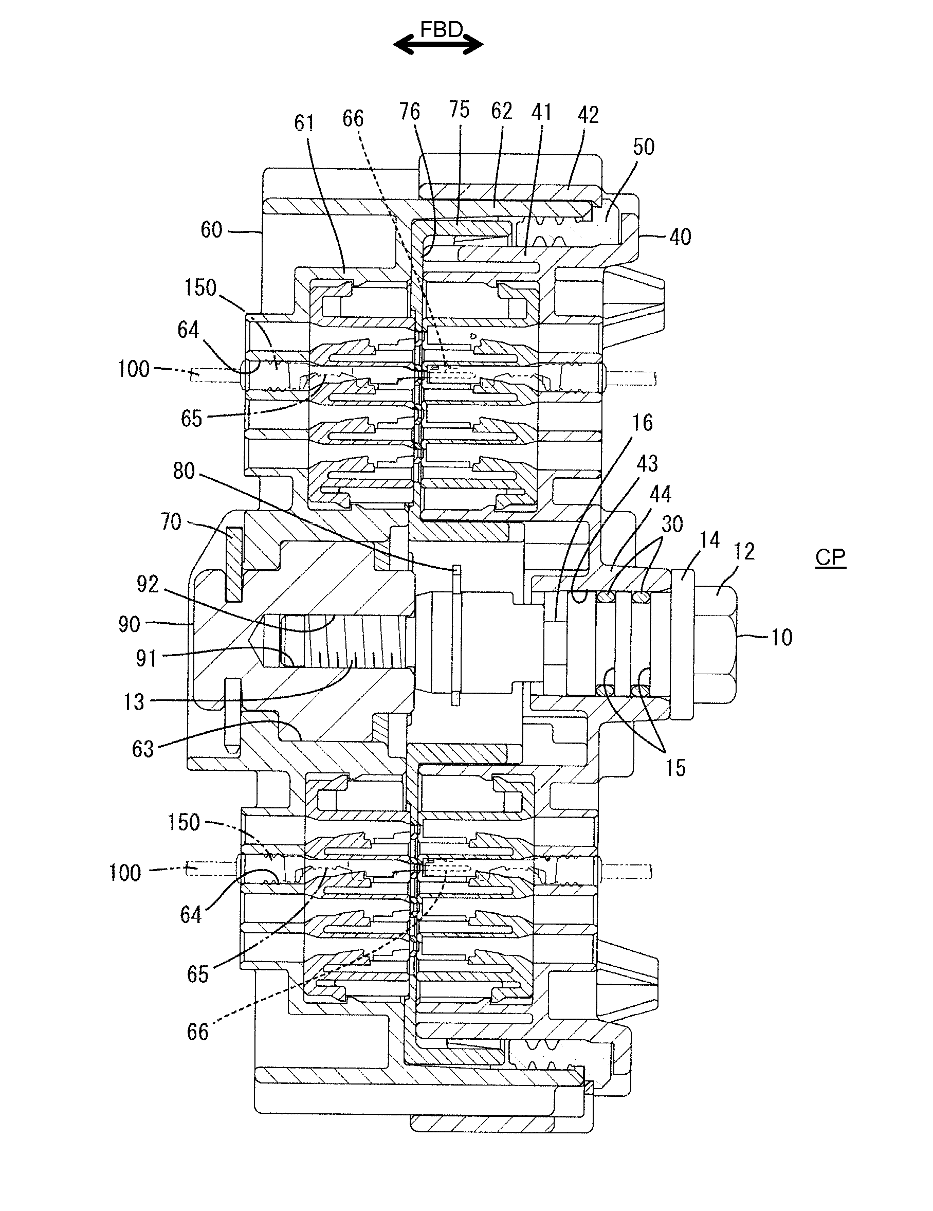
[0034]A connector assembly in accordance with the invention has first and second connectors 40, 60 that are connectable to each other, as shown in FIGS. 7 and 8. A bolt 10 is mounted in the first connector 40 and a nut 90 is mounted in the second connector 60. The bolt 10 can be screwed into the nut 90 for connecting the first and second connectors 40, 60 to each other. In the following description, connection surfaces of the first and second connectors 40, 60 are referred to as front ends concerning forward and backward directions FBD.

[0035]As shown in FIG. 8, the second connector 60 includes a substantially flat block shaped second housing 61 and a substantially tubular receptacle 62 projects forward from the peripheral edge of the front end of the second housing 61. A nut mounting hole 63 is provided in a substantially central part of the second housing 61. The nut 90 is inserted into the nut mounting hole 63 and retained by a stopper 70. A bolt receiving bore 91 extends in forwa...


PUM


Abstract

A bolt (10) includes a flange (14) that bulges radially out near a head (12) at one axial end. The flange (14) contacts a second connector (60) at a proper connection to prevent further tightening. A stepped recess (16) is located between the head (12) and a screw portion (13), and is recessed sufficiently to fracture when an excessive tightening torque is applied. A retaining groove (18) is located between the stepped recess (16) and the screw portion (13) and is recessed radially inwardly and receives a retaining ring (80) for preventing detachment of the bolt (10) from a first connector (40) by contacting the first connector (40) before connection. Seal grooves (15) are located between the stepped recess (16) and the flange (14) for receiving seals (30) to be held in close contact with the first connector (40) in a liquid-tight manner at the time of proper connection.

Description

BACKGROUND OF THE INVENTION[0001]1. Field of the Invention[0002]The invention relates to a connector connecting bolt, a connector to be connected by that bolt and a corresponding connector assembly.[0003]2. Description of the Related Art[0004]U.S. Pat. No. 6,575,787 discloses a connector connecting bolt and a connector to be connected by that bolt. The bolt includes a shaft that is long in an axial direction. A head is provided at one axial end of the shaft and externally threads are provided on the other axial end part of the shaft. The bolt is mounted in a first connector. First and second connectors are fit lightly together and a rotational force is applied to the head with the bolt mounted in the first connector. Thus, the externally threads engage threadedly with a nut mounted in the second connector. The second connector is pulled toward the first connector as the externally thread screw into the nut. As a result, the first and second connectors are connected properly. A seal ...

Claims


Application Information

Patent Timeline
Patent Type & Authority Applications(United States)
IPC IPC(8): H01R13/621F16B35/00
CPCF16B33/004F16B35/048F16B35/00H01R13/6215
Inventor SHIBATA, TAKAHIRO
Owner SUMITOMO WIRING SYST LTD
Why Eureka
Try Eureka