Connection system with keyboard-video-mouse device

a technology of video mouse and connection system, which is applied in the field of connection system, can solve the problems of time-consuming and laborious in finding the desired cable in the system, and achieve the effect of reducing labor intensity and time-consuming

Inactive Publication Date: 2013-10-03
HONG FU JIN PRECISION IND (SHENZHEN) CO LTD +1
View PDF0 Cites 1 Cited by
  • Summary
  • Abstract
  • Description
  • Claims
  • Application Information

AI Technical Summary

Problems solved by technology

Finding a desired cable in the system may be tedious and time consuming.

Method used


Image

  • Connection system with keyboard-video-mouse device
  • Connection system with keyboard-video-mouse device
  • Connection system with keyboard-video-mouse device

Examples


first embodiment

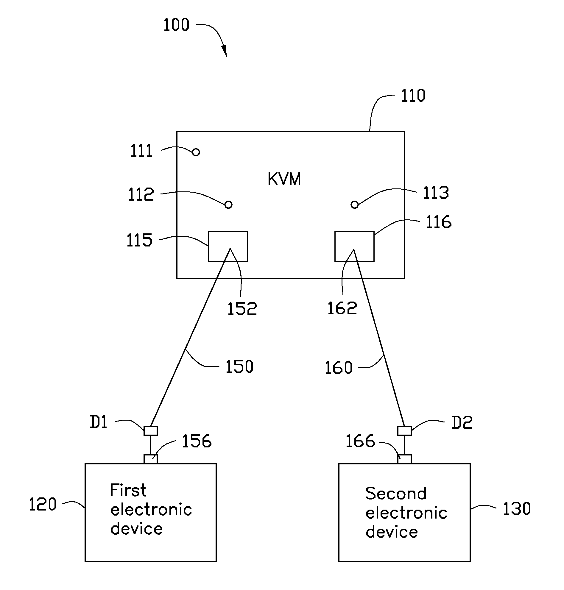
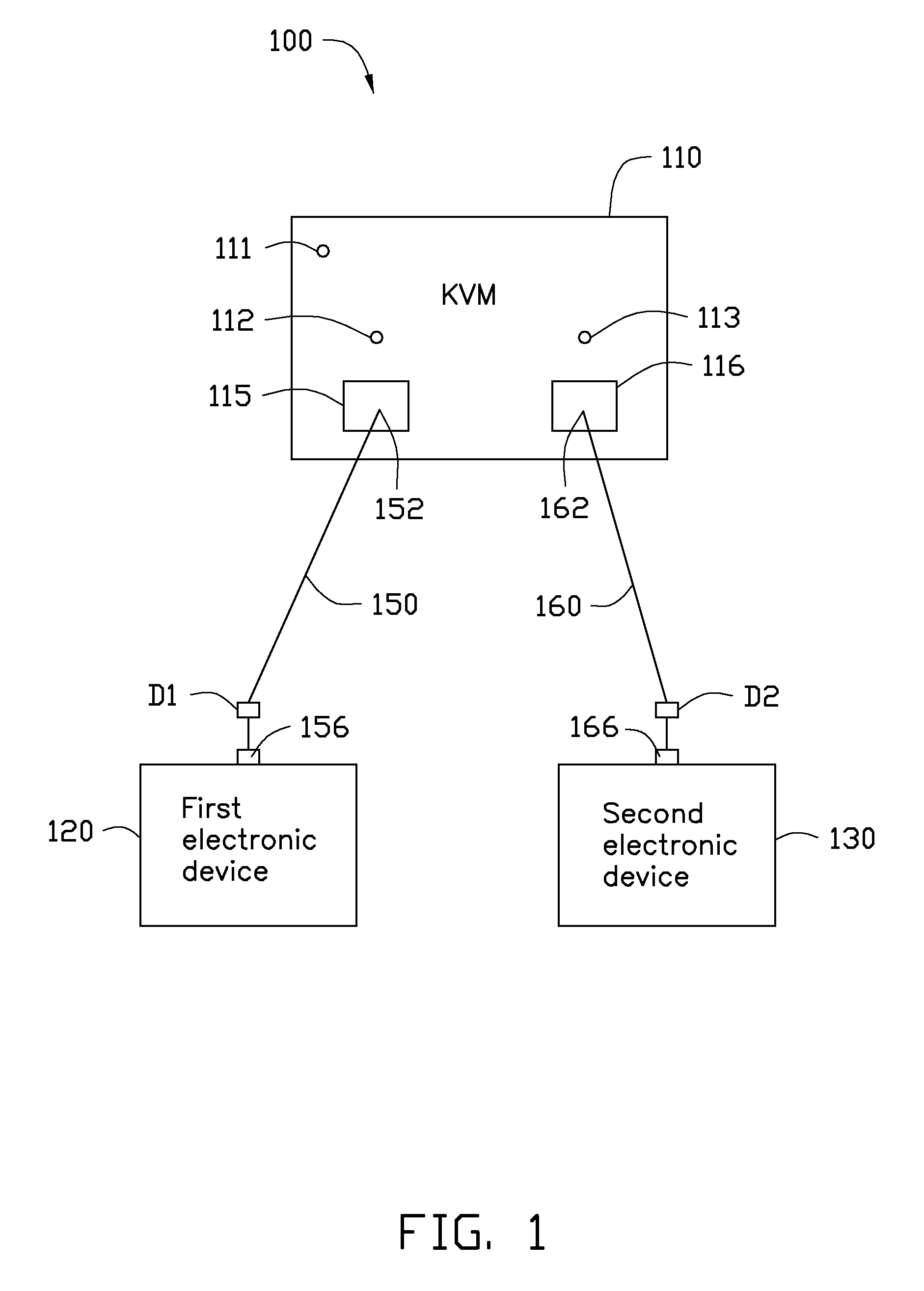
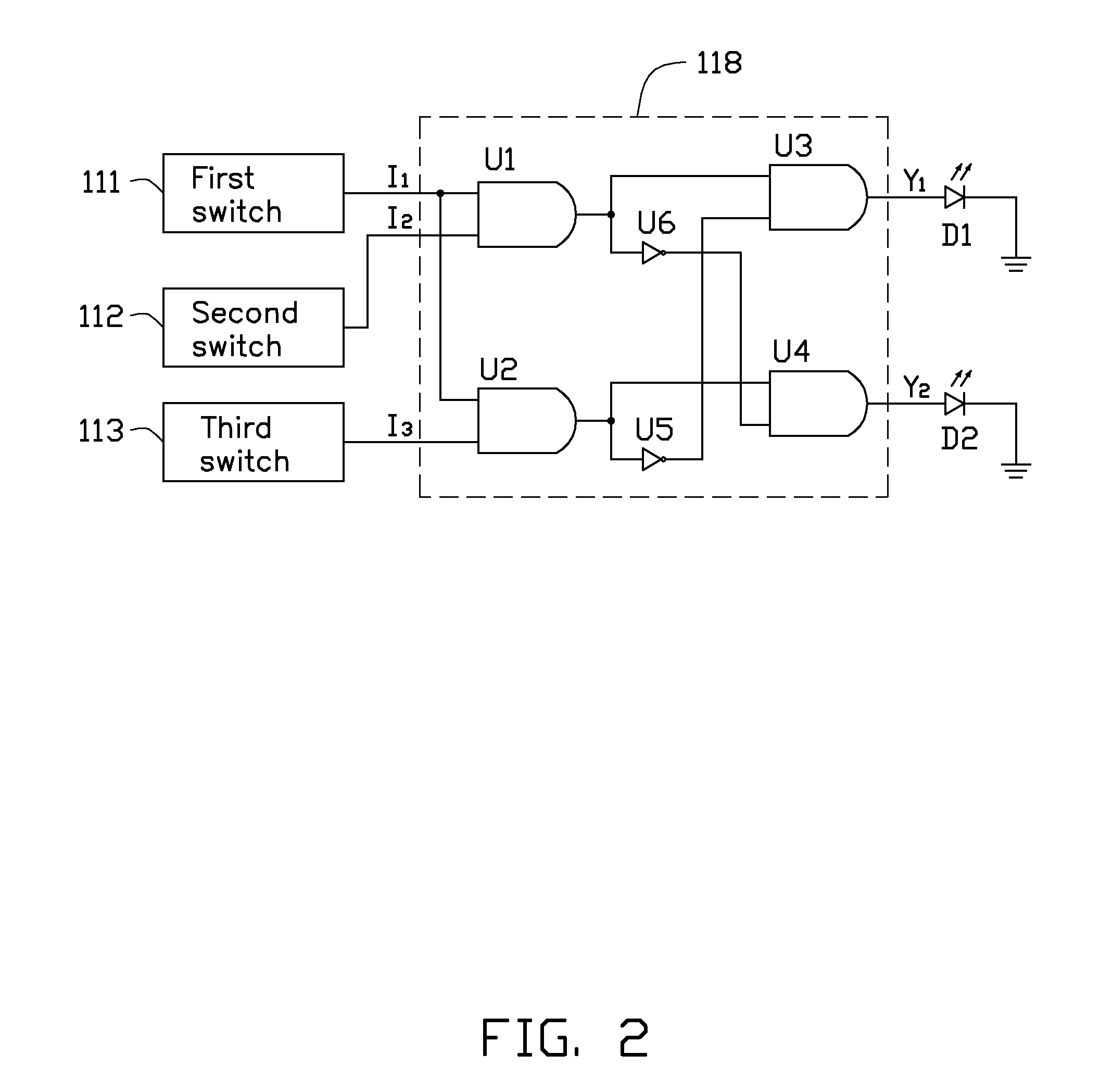
[0012]Referring to FIG. 2, a logic circuit118 of the KVM device 110 includes a first AND gate U1, a second AND gate U2, a third AND gate U3, a fourth AND gate U4, a first NOT gate U5, and a second NOT gate U6. A first input terminal of the first AND gate U1 functions as a first input terminal of the logic circuit 118, and is connected to the first switch 111. A second input terminal of the first AND gate U1 functions as a second input terminal of the logic circuit 118, and is connected to the second switch 112. A first input terminal of the second AND gate U2 is connected to the first input terminal of the first AND gate U1. A second input terminal of the second AND gate U2 functions as a third input terminal of the logic circuit 118, and is connected to the third switch 113. A first input terminal of the third AND gate U3 is connected to an output terminal of the first AND gate U1. A second input terminal of the third AND gate U3 is connected to an output terminal of the first NOT ...

second embodiment

[0014]Referring to FIG. 3, a logic circuit 119 of the KVM device 110 includes a first AND gate U7, a second AND gate U8, a first NOT gate U9, and a second NOT gate U10. A first input terminal of the first AND gate U7 functions as a first input terminal of the logic circuit 119, and is connected to the first switch 111. A second input terminal of the first AND gate U7 functions as a second input terminal of the logic circuit 119, and is connected to the second switch 112. A third input terminal of the first AND gate U7 is connected to an output terminal of the first NOT gate U9. A first input terminal of the second AND gate U8 is connected to the first input terminal of the first AND gate U7. A second input terminal of the second AND gate U8 functions as a third input terminal of the logic circuit 119, and is connected to the third switch 113. A third input terminal of the second AND gate U8 is connected to an output terminal of the second NOT gate U10. An input terminal of the first...


PUM


Abstract

A connection system includes a keyboard-video-mouse (KVM) device, first and second electronic devices, first and second cables. The first cable includes a first terminal connected to the KVM device, a second terminal connected to the first electronic device, and a first indicator positioned on the first cable and close to the second terminal. The second cable includes a third terminal connected to the KVM device, a fourth terminal connected to the second electronic device, and a second indicator positioned on the second cable and close to the fourth terminal. The KVM device includes first to third switches, and a logic circuit connected to the first to third switches and the first and second indicators. When the first and second switches are closed, the first indicator is lit by the logic circuit. When the first and third switches are closed, the second indicator is lit by the logic circuit.

Description

BACKGROUND[0001]1. Technical Field[0002]The present disclosure relates to connection systems, and more particularly to a connection system including a keyboard-video-mouse (KVM) device.[0003]2. Description of Related Art[0004]A KVM device allows users using a keyboard, a video monitor, and a mouse to control a plurality of electronic devices, such as computer, by transmitting signals between the keyboard, the video monitor, the mouse, and the electronic devices. However, each electronic device is connected to a power supply, a network, etc, besides the KVM device. Therefore, there is a plurality of cables in the system. Finding a desired cable in the system may be tedious and time consuming.BRIEF DESCRIPTION OF THE DRAWINGS[0005]Many aspects of the present disclosure can be better understood with reference to the following drawings. The components in the drawings are not necessarily drawn to scale, the emphasis instead being placed upon clearly illustrating the principles of the pre...

Claims


Application Information

Patent Timeline
Patent Type & Authority Applications(United States)
IPC IPC(8): G06F13/12
CPCG09G2370/24G06F3/023
Inventor GAO, ZHENG-XIN
Owner HONG FU JIN PRECISION IND (SHENZHEN) CO LTD
Why Eureka
Try Eureka