
Starter jig

a jig and starter technology, applied in the field of new wood and composite shake or shingle jigs, can solve the problemsavoiding the use of tools, and wasting time, and achieving the effects of reducing the overall installation time, and being easy to us

Inactive Publication Date: 2013-02-28
GRANITE STATE INNOVATIONS
View PDF35 Cites 1 Cited by
  • Summary
  • Abstract
  • Description
  • Claims
  • Application Information

AI Technical Summary

Benefits of technology

The present invention provides a shake and shingle starter jig that is easy and accurate to install, while also being efficient in preventing water from backing up against the building. This jig can be easily removed after installation of the first course of shakes. Additionally, the invention helps to decrease the installation time of shakes or shingles while still maintaining the desired installation accuracy.

Problems solved by technology

Such technique, if executed properly, can be quite accurate but is generally very tedious and time consuming.
While other methods and processes, which are known and utilized to assist with the installation of the first or the starter course of shakes to the side wall of a house or a building, have been the standard, none of these currently known methods offer the desired accuracy, ease of installation, and a reduction in the overall installation time.

Method used


Image

  • Starter jig
  • Starter jig
  • Starter jig

Examples


first embodiment

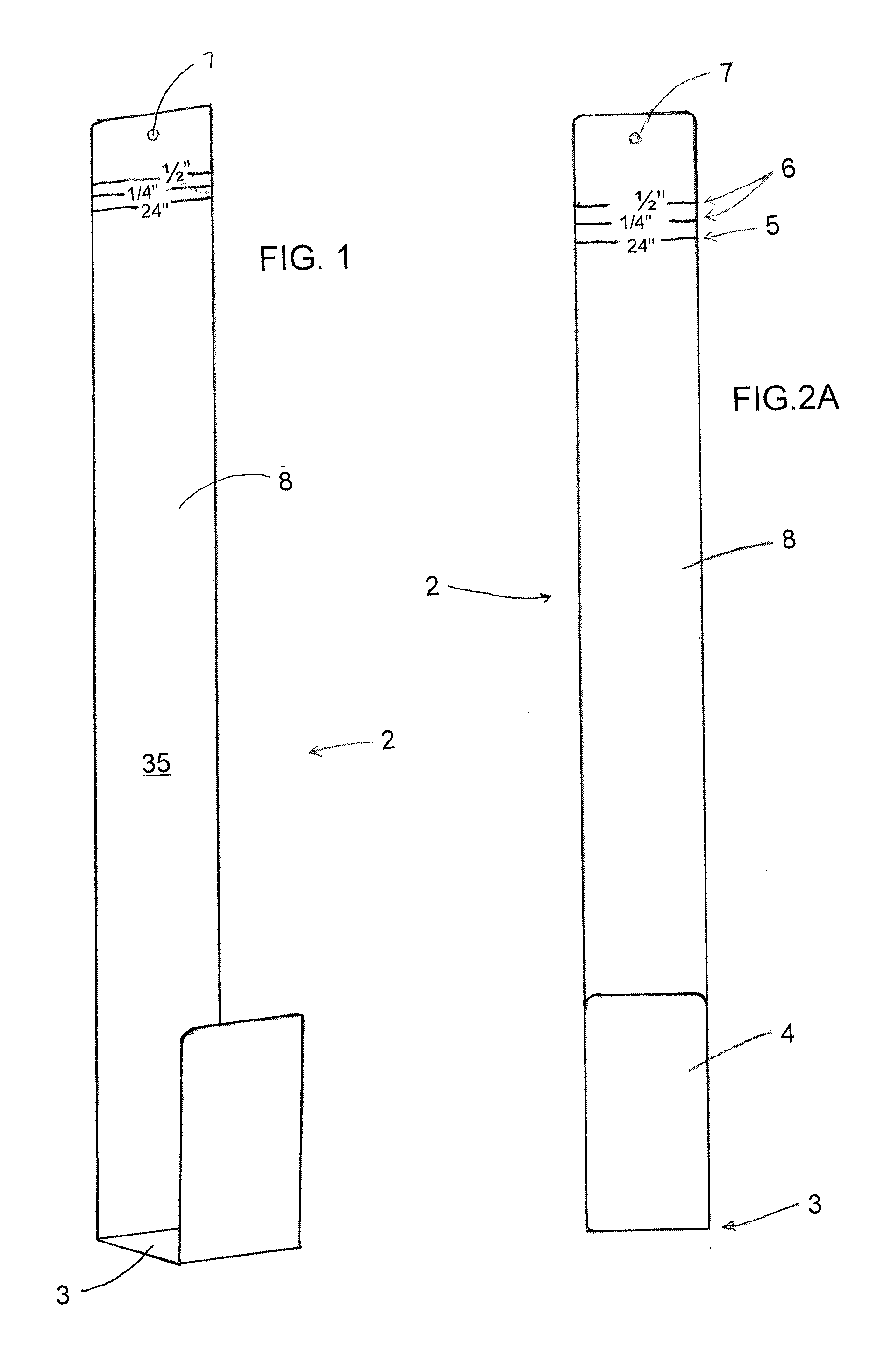
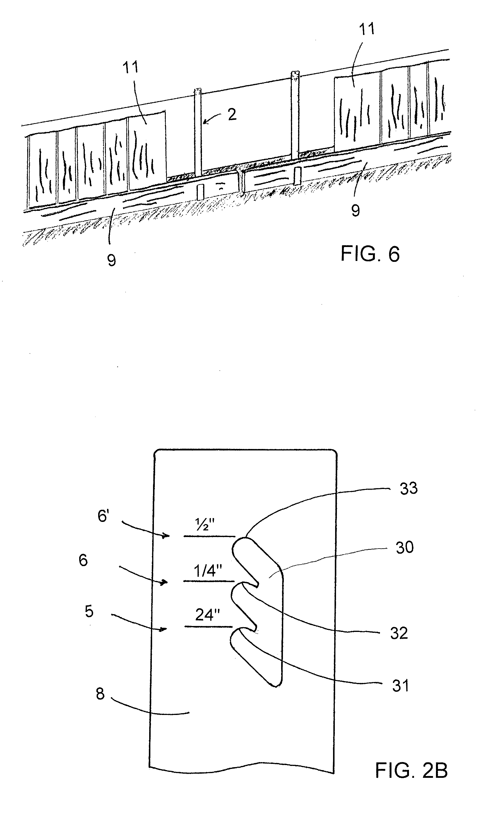
[0047]A slight variation of the shake starter jig 2 is shown in FIG. 2B and this variation also includes an anchor leg 8 which has an upper section that includes both the main position indicator 5 as well as a pair of adjustment markers 6 which form a pair of adjusted positions for the shake starter jig 2. According to this embodiment, the main position indicator 5 and the pair of adjustment markers 6 are generally used for the same purposes discussed above. Since this variation is quite similar to the first embodiment, only the difference between this variation and the previous embodiment will be discussed in detail.

[0048]As shown in FIG. 2B, instead of having a single circular anchor hole 7, the anchor hole comprises an aperture 30 having three cup shaped jig supports 31, 32, 33 for supporting the starter jig 2 at a different distance from the bottom of the ledger shelf 3. The lowermost jig support 31 is associated with the main position indicator and is located a desired distance...

second embodiment

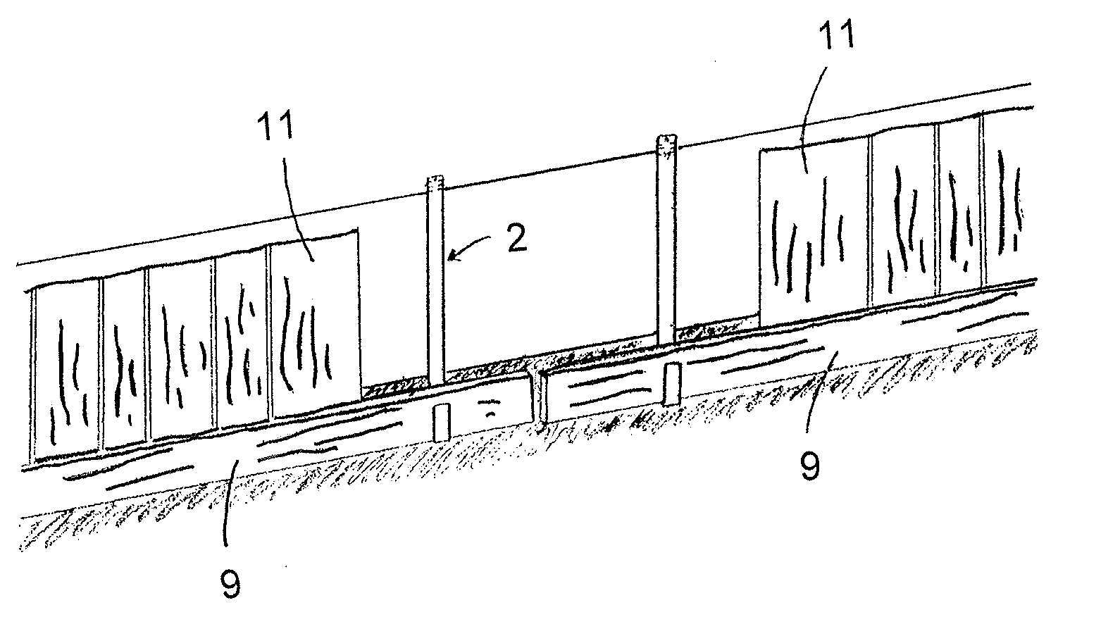
[0052]One difference with respect to the anchor leg 8 is that the anchor leg 8, comprises three sections, namely, the first section 8′ which supports the main position indicator 5 and the first and second adjustment markers 6, a second section 8″ which is integral with the ledger shelf 3, and an intermediate section 8″ which couples were interconnects the first section 8′ with the second section 8″. As can be seen in FIGS. 7 and 8, the intermediate section 8″ forms an angle of between approximately 100 and 135 degrees, more preferably an angle of about 115° or so, with the front surface 35 of the first section 8′, while the intermediate section 8″ forms an angle of between approximately 100 and 135 degrees, more preferably an angle of about 115° or so, with the second section 8′″ of the anchor leg 8 to thereby form a stepped out section 18 for the shake starter jig 2, the purpose of which will be become readily apparent in view of the following description.

[0053]A suspension mechan...


PUM


Abstract

A method and system for installing a first course of shakes or shingles on either a wall or a roof of a structure. The shake starter jig comprises an anchor leg with a first end and a second end, a suspension mechanism located adjacent the first end of the anchor leg to facilitate securing the shake starter jig to a desired surface, a ledger shelf supported adjacent the second end of the anchor leg, a ledger support rigidly affixed to a remote end of the ledger shelf, the second end of the anchor leg, the ledger shelf and the ledger support are all sized so as to facilitate receiving and accommodating a ledger board therebetween. The suspension mechanism is located a predefined distance away from the ledger shelf so as to facilitate spacing the ledger shelf a desired distance from a level line.

Description

FIELD OF INVENTION[0001]The present invention relates to a novel wood and composite shake or shingle jig (with composite, meaning any concrete fiber, plastic, or any other artificial or synthetic material) for use in a siding or a roofing installation, which would be used in multiples and with a ledger board to facilitate proper installation of the first or bottom double course of horizontal shakes and shingles when commencing the process of either siding or roofing a desired structure, such as a house or a building.BACKGROUND OF INVENTION[0002]There are a variety of different techniques currently being utilized by carpenters and / or installers when installing the first or the starter course of shakes to a wall during siding of a house or building. One common technique is to cut the shakes at an equal height and then individually fasten shakes along a level horizontal chalk line, generally “snapped” from one vertical edge or corner of the house or the building to the opposite vertica...

Claims


Application Information

Patent Timeline
Patent Type & Authority Applications(United States)
IPC IPC(8): E04F21/18
CPCE04F21/18E04F21/1855
Inventor DUQUETTE, DAN R.BRIGGEMAN, GERALD F.
Owner GRANITE STATE INNOVATIONS
Learn More