
Microcontroller and method for controlling power indicator

Inactive Publication Date: 2012-12-20
HONG FU JIN PRECISION IND (SHENZHEN) CO LTD +1
View PDF0 Cites 0 Cited by
  • Summary
  • Abstract
  • Description
  • Claims
  • Application Information

AI Technical Summary

Benefits of technology

[0004]A power supply device is an essential component of a computer, the power supply device provides power to start the computer. It is very important for a user to know a status of the power supply device when the user uses the computer. However, at present, the status of the power supply device is manually detected. For example, the user can manually set parameters using a specific application to detect the status of the power supply device at 10:00 AM. The status of the power supply device is not detected in real-time when the user uses the computer. This is tedious and time consuming and thus, there is room for improvement in the art.

Problems solved by technology

This is tedious and time consuming and thus, there is room for improvement in the art.

Method used


Image

  • Microcontroller and method for controlling power indicator
  • Microcontroller and method for controlling power indicator
  • Microcontroller and method for controlling power indicator

Examples


Embodiment Construction

[0008]The disclosure is illustrated by way of examples and not by way of limitation in the figures of the accompanying drawings in which like references indicate similar elements. It should be noted that references to “an” or “one” embodiment in this disclosure are not necessarily to the same embodiment, and such references mean at least one.

[0009]In general, the word “module”, as used herein, refers to logic embodied in hardware or firmware, or to a collection of software instructions, written in a programming language, such as, Java, C, or assembly. One or more software instructions in the modules may be embedded in firmware, such as in an EPROM. The modules described herein may be implemented as either software and / or hardware modules and may be stored in any type of non-transitory computing device-readable medium or other storage device. Some non-limiting examples of non-transitory computing device-readable media include CDs, DVDs, BLU-RAY, flash memory, and hard disk drives.

[00...


PUM


Abstract

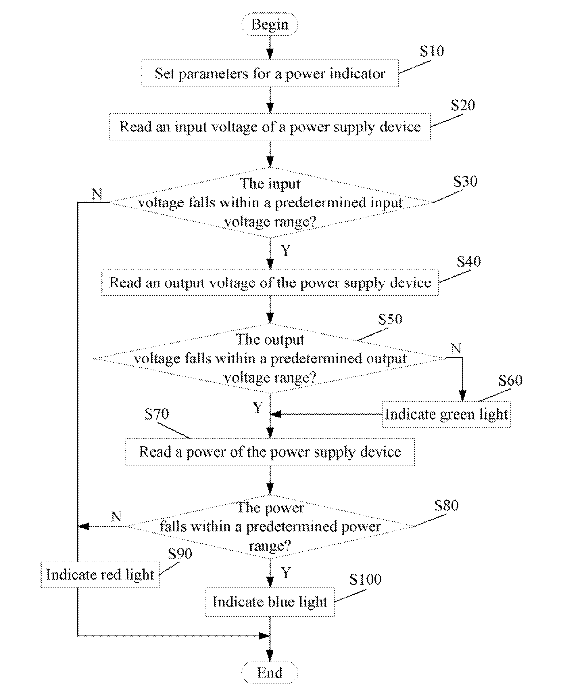
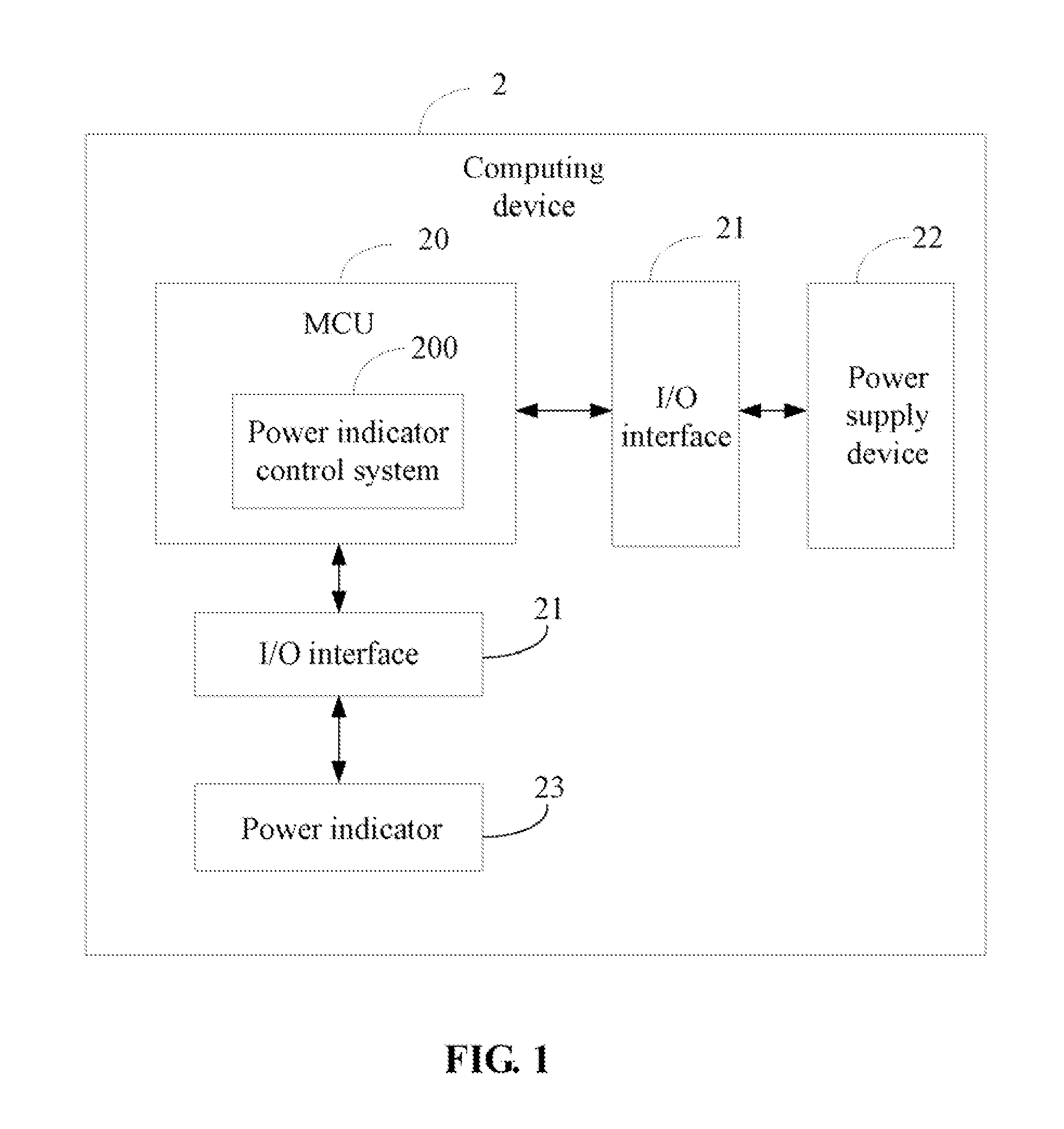
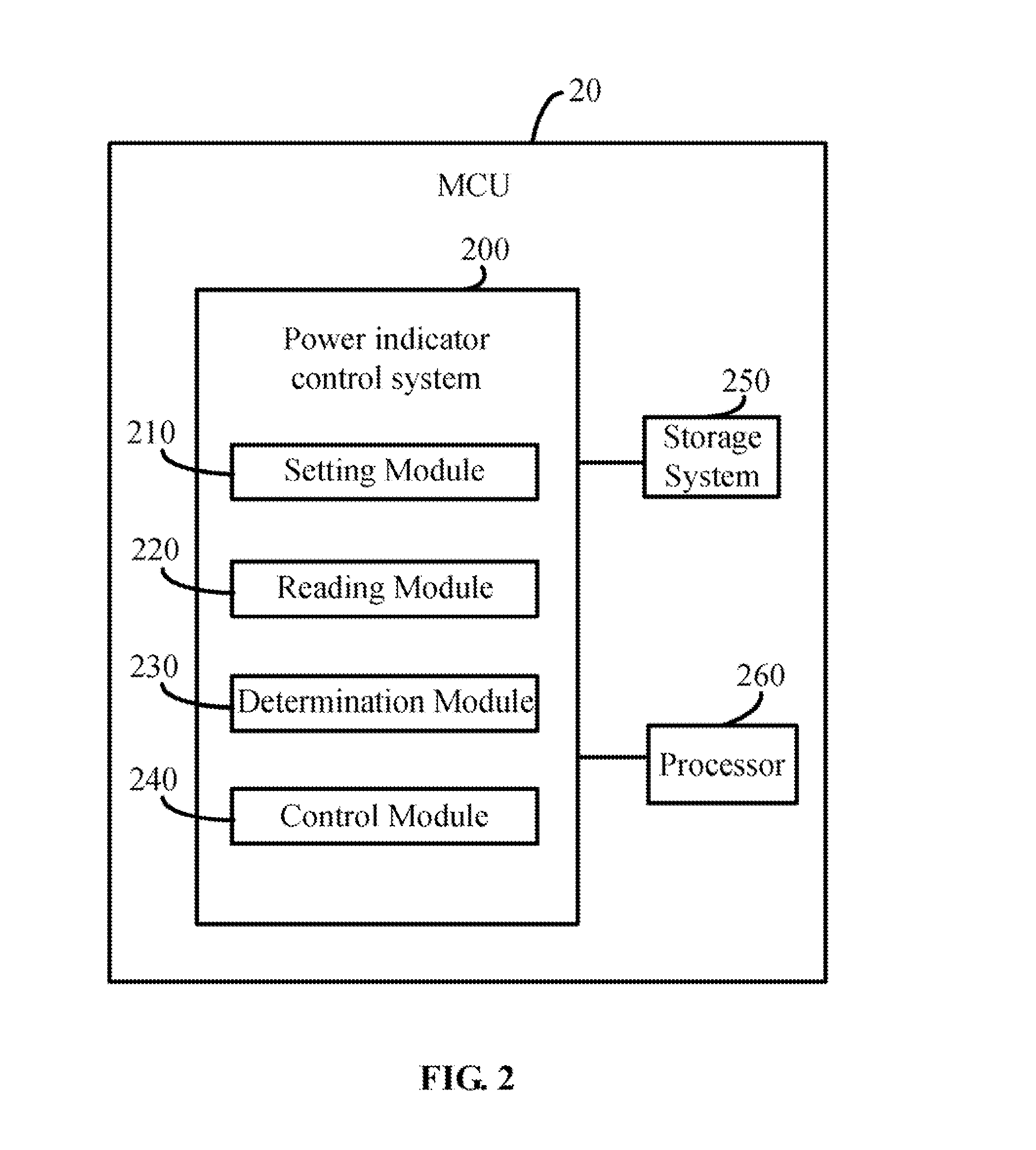
A microcontroller (MCU) and method controls a power indicator. The MCU reads an input voltage of a power supply device, reads an output voltage of the power supply device, and reads a power of the supply device. The MCU determines if the read input voltage of the power supply device falls within a predetermined input voltage range, determines if the read output voltage of the power supply device falls within a predetermined output voltage range, and determines if the read power of the power supply device falls within a predetermined power range. The MCU controls the power indictor to indicate a light according to a determination result of the power supply device.

Description

BACKGROUND[0001]1. Technical Field[0002]The embodiments of the present disclosure relate to control technology of electronic devices, and particularly to a microcontroller and method for controlling a power indicator.[0003]2. Description of Related Art[0004]A power supply device is an essential component of a computer, the power supply device provides power to start the computer. It is very important for a user to know a status of the power supply device when the user uses the computer. However, at present, the status of the power supply device is manually detected. For example, the user can manually set parameters using a specific application to detect the status of the power supply device at 10:00 AM. The status of the power supply device is not detected in real-time when the user uses the computer. This is tedious and time consuming and thus, there is room for improvement in the art.BRIEF DESCRIPTION OF THE DRAWINGS[0005]FIG. 1 is a system view of one embodiment of a computing de...

Claims


Application Information

Patent Timeline
IPC IPC(8): G06F1/26G06F1/28
CPCG06F11/3055G06F11/3058G06F11/325G06F1/28H05B33/0806
Inventor CONG, WEI-DONG
Owner HONG FU JIN PRECISION IND (SHENZHEN) CO LTD
Learn More