Rotary electric machine

a rotary electric machine and electric motor technology, applied in the direction of dynamo-electric machines, electrical apparatus, windings, etc., can solve the problems of inconvenient operation of respective portions of the rotary electric machin

Inactive Publication Date: 2013-10-17
TOYOTA JIDOSHA KK
View PDF5 Cites 40 Cited by
  • Summary
  • Abstract
  • Description
  • Claims
  • Application Information

AI Technical Summary

Benefits of technology

[0011]The neutral line is made, in the region thereof that is in contact with the temperature sensor, equal in cross-sectional area to the coil conductor, whereby the electric current densi...

Problems solved by technology

This rise in temperature may cause inconveniences...

Method used


Image

  • Rotary electric machine
  • Rotary electric machine
  • Rotary electric machine

Examples


Embodiment Construction

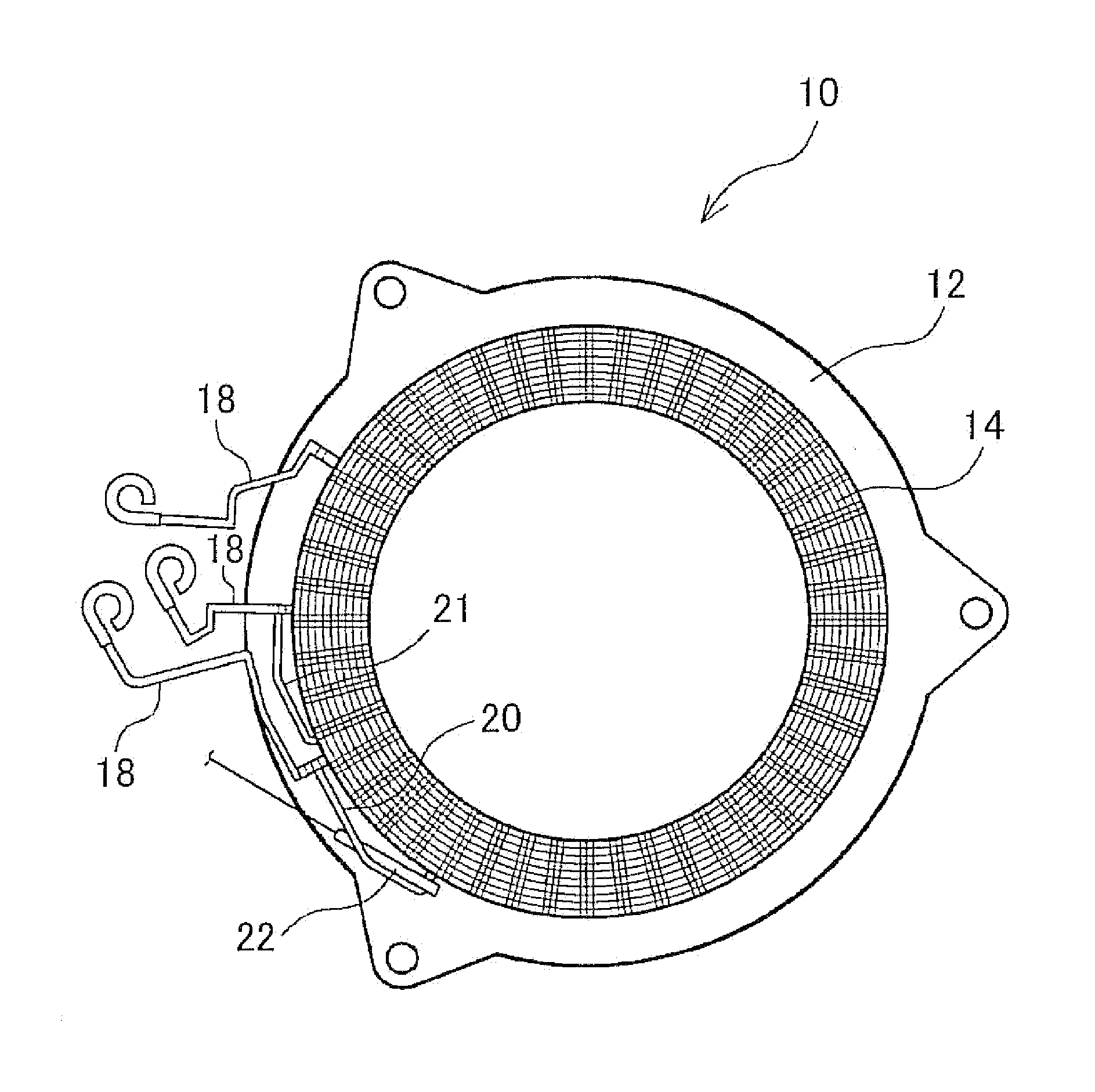
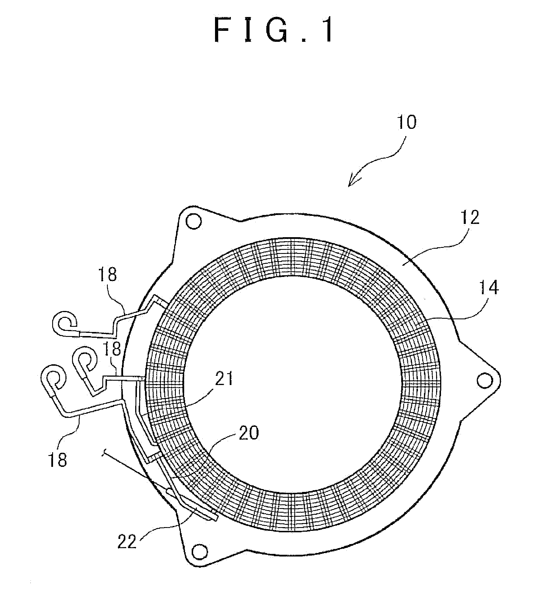
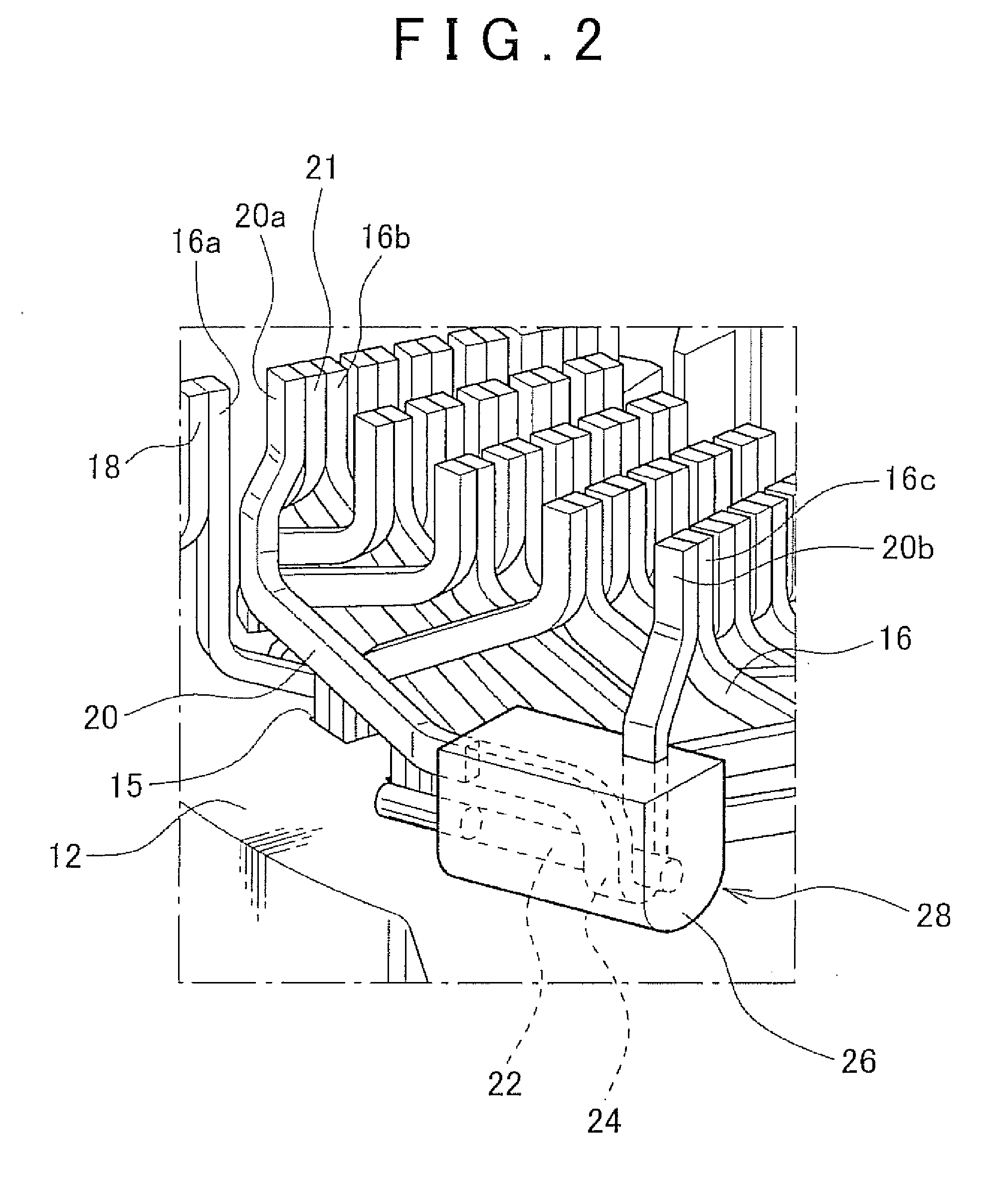
[0015]An embodiment of the invention will be described hereinafter with reference to the drawings. FIG. 1 is a diagram showing an appearance of a stator 10 of a rotary electric machine as viewed from a direction of an axis of rotation of the rotary electric machine. The stator 10 has a generally cylindrical stator core 12, and coils 14 that are wound around the stator core 12. Convex portions are arranged along a circumferential direction on an inner periphery of the cylinder of the stator core 12. Each region between adjacent ones of the convex portions is called a slot 15, and coil conductors 16 (see FIG. 2) are inserted into this slot 15. The conductor for the coil, or the coil conductor, is, for example, a flat-type conductor that is oblong in cross-section. After being bent into a predetermined shape, the coil conductor is inserted into the slot 15 and fitted thereto. The coil conductors are then welded to each other so as to form the coils 14, which are wound around the stator...


PUM


Abstract

A rotary electric machine includes: a coil conductor that is fitted to a core of the rotary electric machine to form a coil; a neutral line connected to a neutral point of the coil; and a temperature sensor, on which the neutral line is wound to be in contact therewith, and that detects a temperature of the neutral line, wherein the neutral line is, in a region thereof that is in contact with the temperature sensor, equal in cross-sectional area to the coil conductor.

Description

INCORPORATION BY REFERENCE[0001]The disclosure of Japanese Patent Application No. 2012-089831 filed on Apr. 11, 2012 including the specification, drawings and abstract is incorporated herein by reference in its entirety.BACKGROUND OF THE INVENTION[0002]1. Field of the Invention[0003]The invention relates to a rotary electric machine, and more particularly, to a structure regarding the measurement of a temperature of a coil of a rotary electric machine.[0004]2. Description of Related Art[0005]There are known an electric motor that converts electric energy into rotational kinetic energy, a generator that converts rotational kinetic energy into electric energy, and moreover, an electric machine that functions as both an electric motor and a generator. Each of these electric machines will be referred to hereinafter as a rotary electric machine.[0006]The rotary electric machine has two members that are arranged coaxially with each other and rotate relatively to each other. In general, on...

Claims


Application Information

Patent Timeline
IPC IPC(8): H02K11/00
CPCH02K11/0047H02K3/28H02K11/25
Inventor IKEMOTO, MASAYUKI
Owner TOYOTA JIDOSHA KK
Why Eureka
Try Eureka