Illuminated pole

a technology of illumination poles and poles, which is applied in the direction of electric circuit arrangements, skis, sport apparatus, etc., can solve the problems of not being able to use illumination, not being able to provide illumination, and being quite heavy

Inactive Publication Date: 2013-10-17
DOBLE TELESCOPIC LIGHTING
View PDF6 Cites 15 Cited by
  • Summary
  • Abstract
  • Description
  • Claims
  • Application Information

AI Technical Summary

Benefits of technology

[0021]There are a number of significant advantages arising from the present invention by integration of the illumination source i.e. LED strip with the elongated support element. The elongated support element can be telescopic and collapsible with no interference of the illumination source between extended and retracted configurations. This is quite different from the prior art. There are many prior art devices which incorporate LED's but they are generally in rigid beams or supports. Alternatively, in many cases light sources are attached or adhered to a support element by suitable means such as clips, adhesives etc. This requires complicated and time consuming installation, looks unsightly and in many cases fails to be used because of these issues or loss of various components. In particular, extensive wiring is generally used to position the lighting source on a support element.
[0022]The present invention removes all need for separate wiring or complicated installation techniques. The power source is provided direct to one end of the LED strip for example, with all wiring etc integrated into the LED strip. The telescopic, expandable, collapsible nature of the support element is in no way compromised by the integration of the illumination source and there is no need for complicated mounting equipment for providing an illumination or heat source into the support element, unlike conventional systems.

Problems solved by technology

Generally such forms of illumination are specifically designed for interior or exterior use and cannot be used in various locations.
One of the difficulties associated with outdoors and outdoor activities, particularly in remote locations, is the need for illumination.
In some cases the lamp is powered by fuel or gas which can negate the opportunity for using the illumination inside the structure.
If batteries are used these are generally quite heavy.
If light weight batteries / torches are used they generally provide insufficient illumination or their lifespan may be quite short.
With the inconvenience and safety issues associated with conventional illumination systems, there has not been wide spread acceptance and use.

Method used


Image

  • Illuminated pole
  • Illuminated pole
  • Illuminated pole

Examples


Embodiment Construction

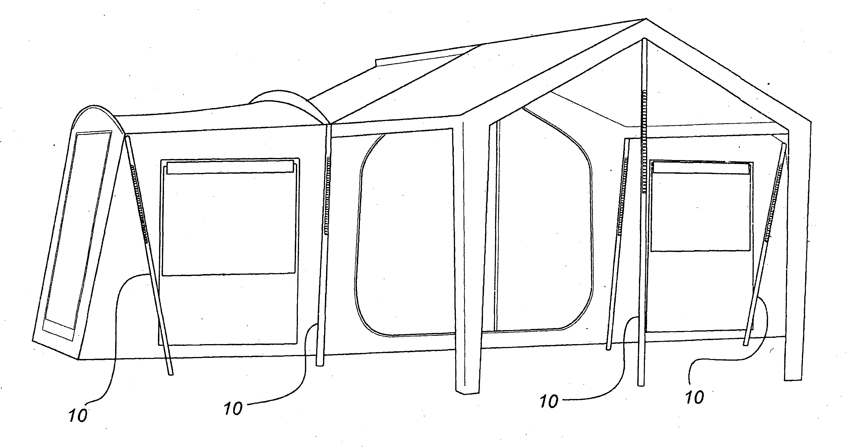
[0034]The present applicants have devised an elegant, robust and cost effective system for illuminating the interior or exterior of a tent, umbrella, awning or shade or similar collapsible structure. The device can be used in conjunction or independently from such structures as it comprises an elongated support element with an illumination source integrated therein. The integration of the illumination source allows the support element to be used in its normal function without interference from the illumination source. In some of the embodiments shown, the elongated support element is a tent pole used to support a tent or similar collapsible structure such as an awning etc. It will be understood by persons skilled in the art, however that the elongated support element maybe provided in other forms.

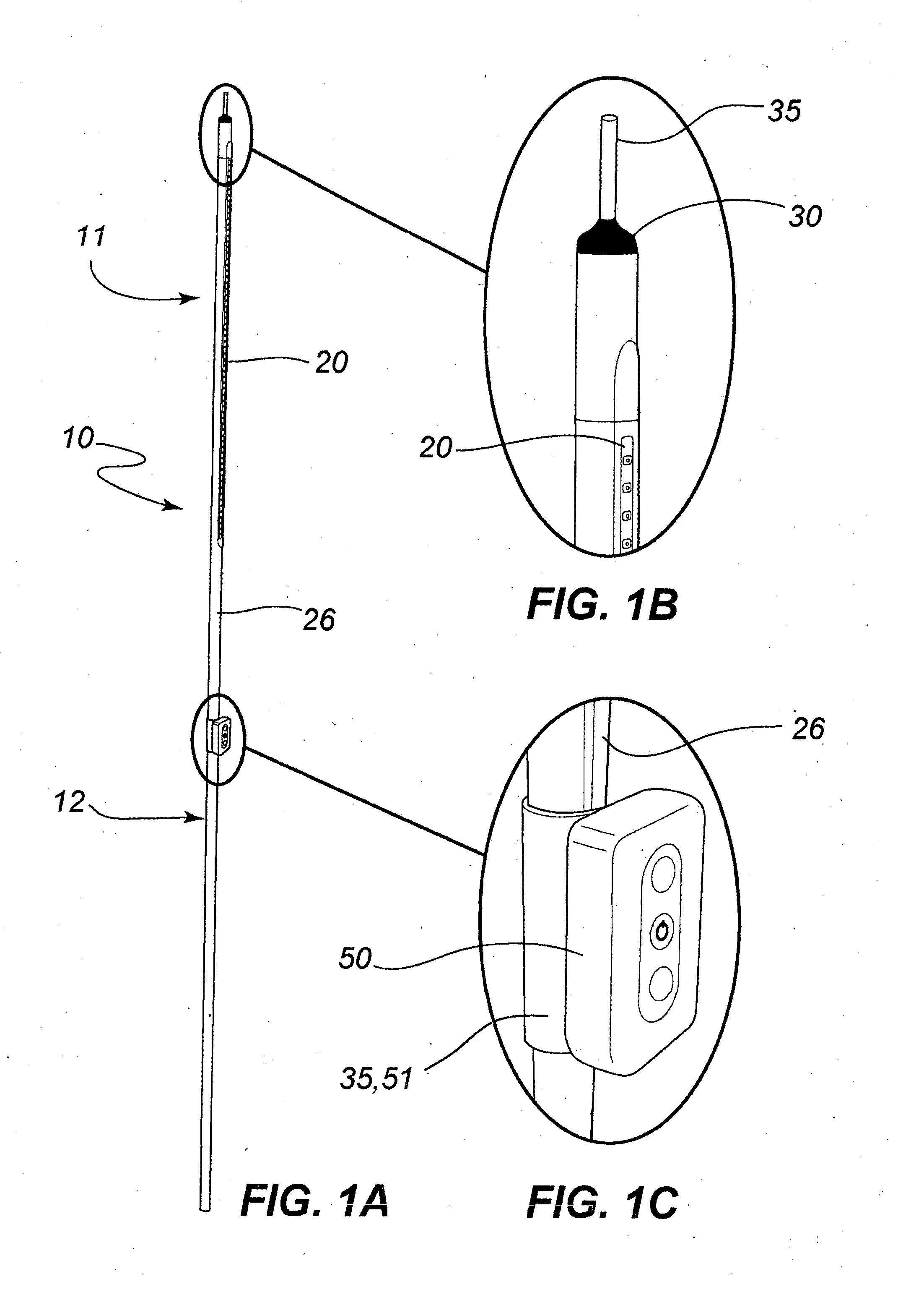
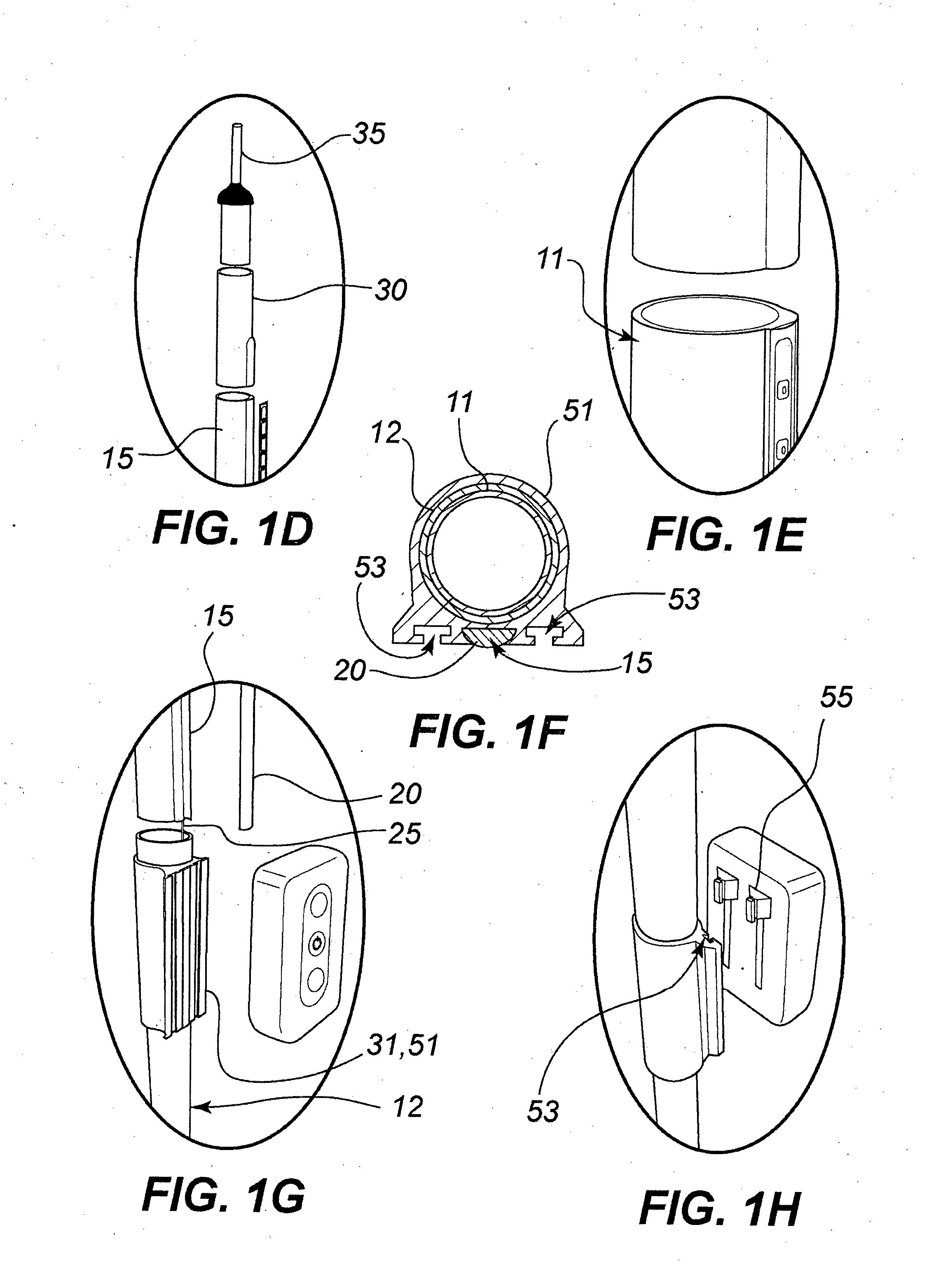
[0035]Refer firstly to the embodiments shown in FIGS. 1A-1H. FIG. 1A shows the inventive device it its extended “in-use” configuration. FIGS. 1B and 10 are detailed views of the upper most ...


PUM


Abstract

The present invention provides an illumination device comprising an elongated support element (10) with an illumination source (20) integrated therein. Preferably the elongated element is collapsible, telescopic or resiliently flexible. It may comprise a plurality of sections (11, 12) which are adapted to reciprocate between a retracted configuration and an extended configuration. The device is particularly suitable for temporary or collapsible structures such as tents, umbrellas, awnings, shades or the like.

Description

TECHNICAL FIELD[0001]The present invention relates to systems and devices for providing illumination and particularly but not only for providing illumination to temporary or collapsible structures such as tents, awnings, etc.BACKGROUND ART[0002]Any discussion of the prior art throughout the specification should in no way be considered as an admission that such prior art is widely known or forms part of common general knowledge in the field.[0003]There are various forms of illumination for both interior and exterior use. Generally such forms of illumination are specifically designed for interior or exterior use and cannot be used in various locations. Further, generally illumination systems are specifically for a particular installation.[0004]One of the difficulties associated with outdoors and outdoor activities, particularly in remote locations, is the need for illumination. While the thought “getting up” and “going down” with the sun is laudable, illumination is generally required...

Claims


Application Information

Patent Timeline
Patent Type & Authority Applications(United States)
IPC IPC(8): F21V21/22F21V33/00
CPCF21V21/22F21V33/006A45B3/04A45B2200/1018A63C11/228A63C2203/14E04H15/10E04H15/60F21L4/04F21S8/08F21S9/02F21S9/032F21S9/043F21V21/0824F21V23/008F21V23/023F21V23/026F21V23/04F21W2111/00F21Y2103/10F21Y2115/10E04H15/46
Inventor DOBLE, SIMON
Owner DOBLE TELESCOPIC LIGHTING
Why Eureka
Try Eureka