Methods for manufacturing slide fastener with overmolded components

a technology of overmolded components and manufacturing methods, which is applied in the direction of domestic slide fasteners, other domestic articles, domestic applications, etc., can solve the problems of weakened zipper assembly that will quickly fail in us

Active Publication Date: 2018-12-04
IDEAL FASTENER CORP
View PDF56 Cites 2 Cited by
  • Summary
  • Abstract
  • Description
  • Claims
  • Application Information

AI Technical Summary

Benefits of technology

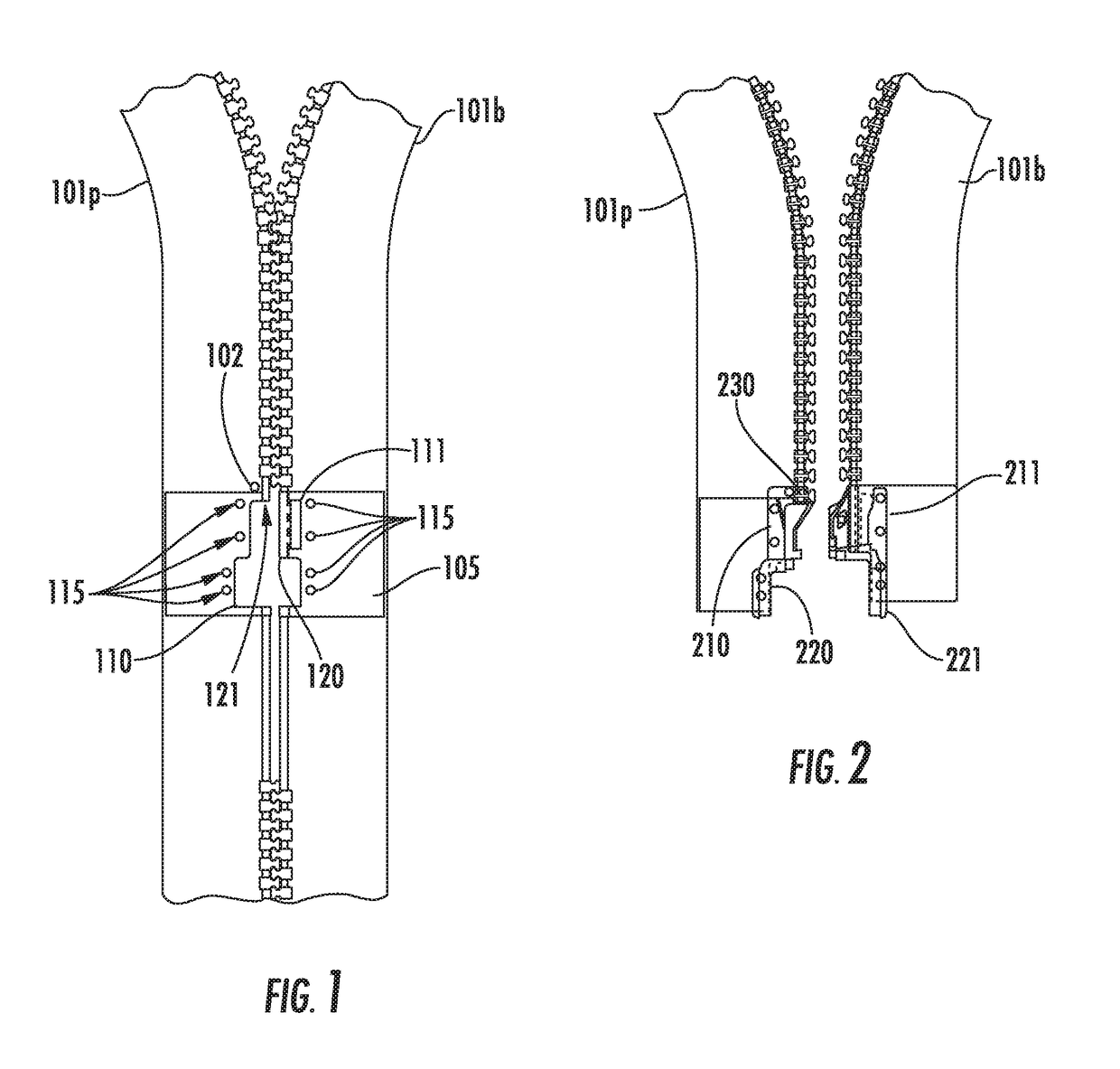
[0010]The zipper of the present invention accomplishes the above objectives as described below. The magnetic catch of the described zipper comprises two over-molded components, one for the “pin” side stringer and a second for the “box” side stringer. The “box” side is the zipper stringer that ordinarily has a box at the bottom end which prevents the slider body from being pulled off of the stringer. The “pin” side is the other zipper stringer that ordinarily has a pin at the bottom end. For a typical separating zipper, when the zipper is opened (the slider body is moved to the fully open position, which is at the pin / box assembly), the pin can be removed from the box, allowing the two zipper stringers to be fully disengaged.
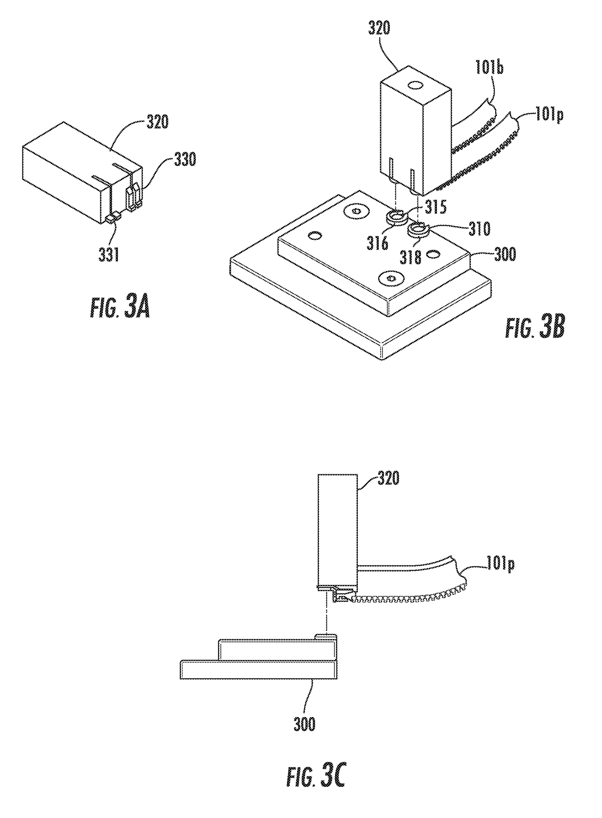
[0012]For the separating zipper described above that uses a magnetic catch, there is a first molded component that is over-molded to the “box” side zipper stringer, and a second molded component that is over-molded to the “pin” side zipper stringer. The two halves of the magnetic catch are later affixed to the over-molded components on the zipper stringers. In order to affix the over-molded components necessary for the attachment of the two halves of the magnetic catch, it is necessary to sever a portion of the cord. Since the severing of the cord from one or both stringers will result in a weakened zipper assembly that will quickly fail in use because it will not be able to resist the lateral forces present in a typical zipper installation. The manufacturing methods disclosed overcome the inherent weakness of a zipper with a severed cord.
[0013]The manufacturing methods disclosed will work with any type of molded zipper; however, the use a special cord results in a stronger zipper. Therefore, a braided cord is preferred over a plain twisted cord. A braided cord is preferably made from synthetic yarns formed from continuous synthetic filaments. A braided cord, unlike twisted yarn cords, consists of a chain of interlaced loops which by nature of the knitting process creates cavities in the surface of the yarn. A braided cord is inherently stronger than a twisted cord, but the cavities on the surface of a braided cord provide further benefits. The over-molded components necessary for the disclosed zipper are made from an acetal resin, and the cavities in the loops of yarn become receptors when the acetal resin is injected to form the over-molded components, thus enhancing the adhesion strength of the acetal to the zipper. Therefore, when the bead cord is partially severed (which is required by the design of the magnetic catch), it is very important to maximize the adhesion strength of the over-molded components to the remaining portion of the cord.

Problems solved by technology

Since the severing of the cord from one or both stringers will result in a weakened zipper assembly that will quickly fail in use because it will not be able to resist the lateral forces present in a typical zipper installation.

Method used


Image

  • Methods for manufacturing slide fastener with overmolded components
  • Methods for manufacturing slide fastener with overmolded components
  • Methods for manufacturing slide fastener with overmolded components

Examples


Embodiment Construction

[0021]As a preliminary matter, it will readily be understood by one having ordinary skill in the relevant art (an “Ordinary Artisan”) that the present invention has broad utility and application. Furthermore, any embodiment discussed and identified as being “preferred” is considered to be part of a best mode contemplated for carrying out the present invention. Other embodiments also may be discussed for additional illustrative purposes in providing a full and enabling disclosure of the present invention. Moreover, many embodiments, such as adaptations, variations, modifications, and equivalent arrangements, will be implicitly disclosed by the embodiments described herein and fall within the scope of the present invention.

[0022]Accordingly, while the present invention is described herein in detail in relation to one or more embodiments, it is to be understood that this disclosure is illustrative and exemplary of the present invention, and is made merely for the purposes of providing ...


PUM

PropertyMeasurementUnit
lengthaaaaaaaaaa
areaaaaaaaaaaa
adhesiveaaaaaaaaaa

Abstract

Zippers components such as a traditional pin and box assembly may be affixed to zipper stringer tapes by a simple injection molding process. When a non-traditional magnetic alignment assembly is used in place of a traditional pin and box assembly, other means are needed to adequately affix the components of the magnetic alignment assembly to the zipper stringer tapes in order to provide a durable finished zipper.

Description

CROSS-REFERENCE TO RELATED APPLICATIONS[0001]The present application is a U.S. continuation patent application of, and claims priority under 35 U.S.C. § 120 to, U.S. nonprovisional patent application Ser. No. 14 / 520,512, filed Oct. 22, 2014, which '512 application issued as U.S. Pat. No. 9,944,028 on Apr. 17, 2018, which '512 application and the patent issuing therefrom are each incorporated by reference herein, and which '512 application is a U.S. nonprovisional patent application of, and claims priority under 35 U.S.C. § 119(e) to, U.S. provisional patent application Ser. No. 61 / 895,221, filed Oct. 24, 2013, which provisional patent application is incorporated by reference herein.COPYRIGHT STATEMENT[0002]All of the material in this patent document is subject to copyright protection under the copyright laws of the United States and of other countries. The copyright owner has no objection to the facsimile reproduction by anyone of the patent document or the patent disclosure, as it ...

Claims


Application Information

Patent Timeline
Patent Type & Authority Patents(United States)
IPC IPC(8): B29D5/00
CPCB29D5/00B29K2995/0008B29D5/02
Inventor DAVIS, GARYMAYO, WILLIAM
Owner IDEAL FASTENER CORP
Why Eureka
Try Eureka