LED bulbs with adjustable light emitting direction

Inactive Publication Date: 2013-10-24
YUAN ZENGGUANG +1
View PDF2 Cites 18 Cited by
  • Summary
  • Abstract
  • Description
  • Claims
  • Application Information

AI Technical Summary

Benefits of technology

[0008]In one aspect, the invention generally relates to an LED light bulb that includes a rotational bulb base. The bulb base has a rotational axis that allows secure locking of the bulb base to a matching bulb power socket through a rotational movement. The light bulb has a hemispherica

Problems solved by technology

Such light bulbs overcome the drawbacks of conventional LED light bulbs that are n

Method used


Image

  • LED bulbs with adjustable light emitting direction
  • LED bulbs with adjustable light emitting direction
  • LED bulbs with adjustable light emitting direction

Examples


Embodiment Construction

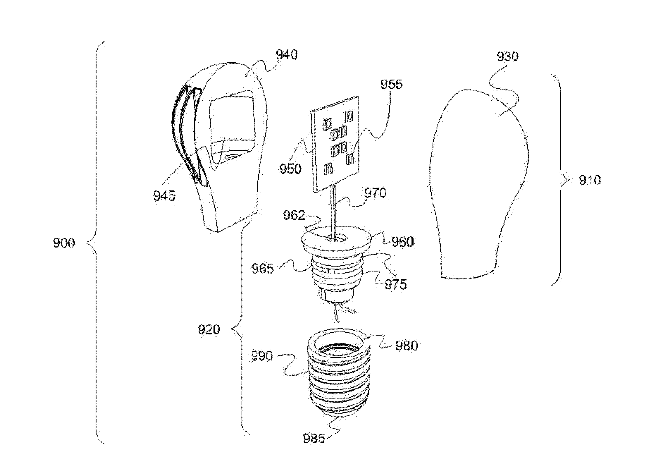
[0030]The invention is based on novel designs that provide modular, interchangeable LED light bulbs that are configured to have an adjustable lateral emission direction. Such light bulbs overcome the drawbacks of conventional LED light bulbs that are not suited for use in certain applications, such as with sideway-mounted light fixtures.

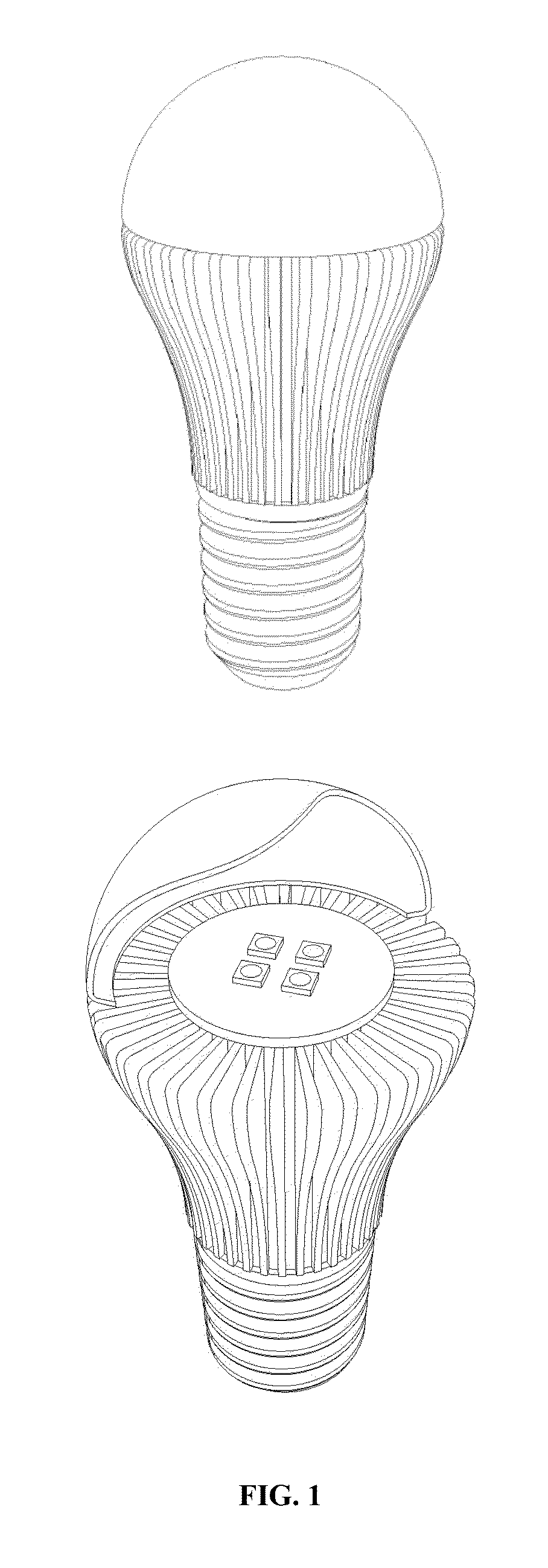
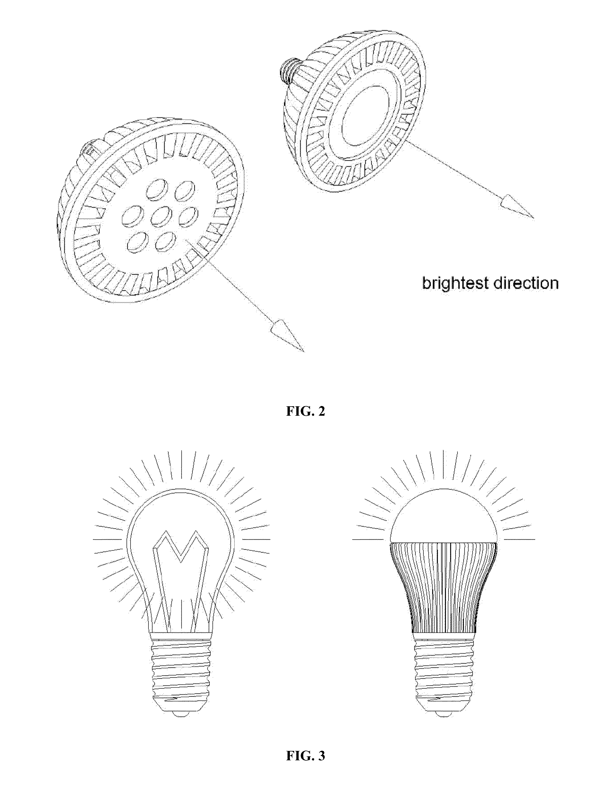
[0031]As shown in FIG. 1A and FIG. 1B, a typical LED bulb has a screw base that is the same as what a conventional bulb has. It also has a circuit board populated with one or several LEDs as light generating devices. On the same circuit board, usually on the opposite side to which the LEDs are mounted are the LED driving circuit and related components. Since LED lamps are damaged if operated at high temperatures, they typically are equipped with heat management elements (e.g., heat sinks or cooling fins) for transferring heat from the electrical components to ambience. In front of the LEDs is often found a diffuser shell to make the light soft. Some ...


PUM


Abstract

The invention provides modular, interchangeable LED light bulbs configured to have an adjustable lateral emission direction. Such light bulbs overcome the drawbacks of conventional LED light bulbs that are not suited for use certain application, such as with sideway mounted light fixtures.

Description

PRIORITY CLAIMS AND RELATED APPLICATIONS[0001]This application claims the benefit of priority from PCT / US11 / 55848, filed Oct. 11, 2011, which claims the benefit of priority from U.S. Provisional Application Ser. No. 61 / 404,869, filed Oct. 12, 2010, the entire content of each of which is incorporated herein by reference for all purposes.TECHNICAL FIELDS OF THE INVENTION[0002]The invention generally relates to LED-based light devices. More particularly, the invention relates to interchangeable, modular LED light bulbs that are configured to have an adjustable lateral emission direction.BACKGROUND OF THE INVENTION[0003]Light-emitting diode (LED) is a semiconductor light source. The light output of individual LEDs is small compared to typical incandescent and compact fluorescent lamps. As a result, LED lamps often use light bulbs that have multiple diodes. In recent years, high power LEDs with higher light output have been developed. LED lamps have become available as replacements for b...

Claims


Application Information

Patent Timeline
IPC IPC(8): F21K99/00
CPCF21K9/1355F21V29/74F21V29/89F21Y2105/10F21K9/23F21K9/65F21Y2115/10F21Y2113/00
Inventor YUAN, ZENGGUANGFONG, CHING
Owner YUAN ZENGGUANG
Why Eureka
Try Eureka