Image pickup lens
- Summary
- Abstract
- Description
- Claims
- Application Information
AI Technical Summary
Benefits of technology
Problems solved by technology
Method used
Image

Examples
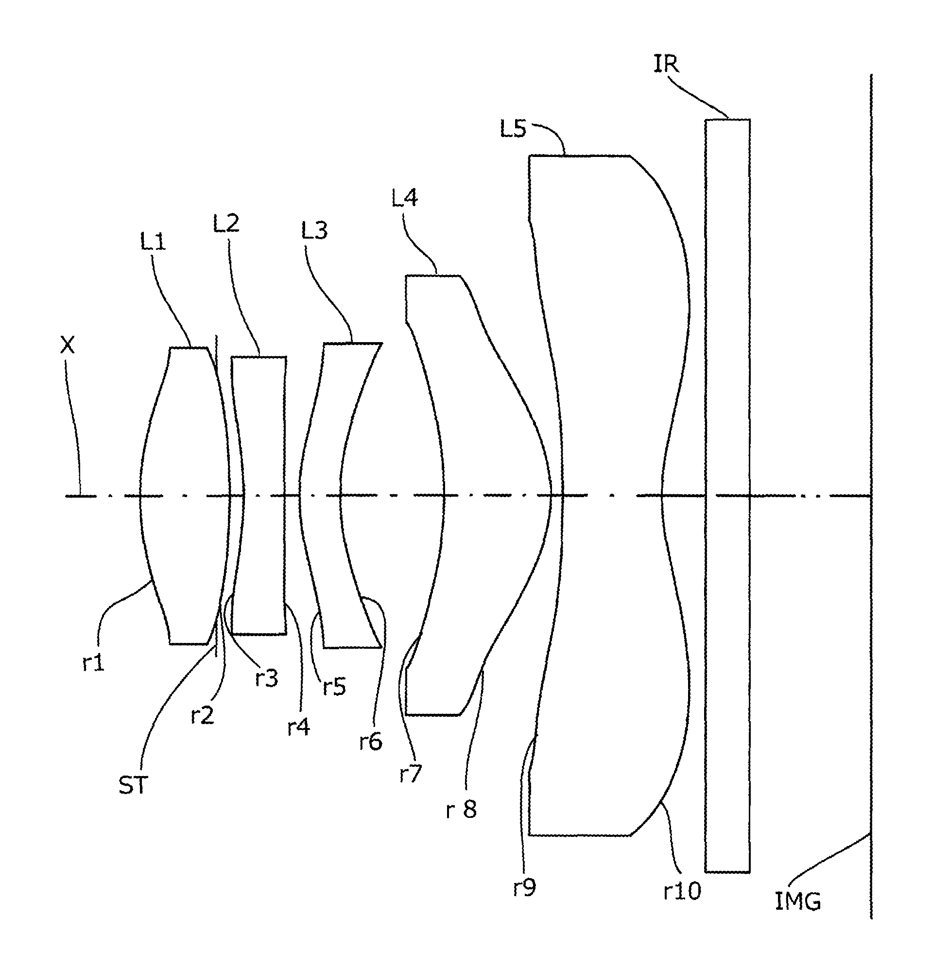
embodiment 1
[0076]Basic lens data will be shown in Table 1 below.
TABLE 1Embodiment 1Unit mmf = 4.114Fno = 2.25ω = 35.54IH = 2.87Surface dataRefractive indexAbbe numberSurface No. iCurvature radius rSurface distance dNdνd(Object surface)InfinityInfinity 1*1.8450.6071.534656.16 2* (Stop)−4.3940.095 3*−2.1090.2801.635523.91 4*−320.1330.101 5*1.3880.2801.635523.91 6*1.5830.727 7*−2.4700.7331.534656.16 8*−0.9770.080 9*−10.8880.6821.509455.8710*1.3780.311Infinity0.31.516864.1712Infinity0.817Image PlaneInfinitySingle lens dataLensStart planeFocal length112.51623−3.3423511.383472.58359−2.357Aspheric data1st surface2nd surface3rd surface4th surface5th surfacek9.747E−010.000E+000.000E+000.000E+000.000E+00A4−5.756E−022.349E−023.022E−01−8.604E−03−3.013E−01A62.002E−02−8.065E−02−3.503E−011.116E−021.126E−01A8−1.532E−015.641E−023.165E−011.753E−02−3.369E−01A101.682E−01−6.549E−027.612E−02−1.747E−024.998E−01A12−1.595E−012.926E−02−4.527E−017.247E−02−2.571E−01A144.881E−023.643E−024.778E−01−5.004E−022.863E−02A165.53...
embodiment 2
[0081]Basic lens data will be shown in Table 2 below.
TABLE 2Embodiment 2Unit mmf = 4.113Fno = 2.25ω = 34.48IH = 2.87Surface dataCurvature radiusSurface distanceRefractive indexAbbe numberSurface No. irdNdνd(Object surface)InfinityInfinity 1*1.8450.6081.534656.16 2* (Stop)−4.3930.095 3*−2.1020.2801.635523.91 4*−212.2770.101 5*1.3880.2801.635523.91 6*1.5830.712 7*−2.4690.7331.534656.16 8*−0.9770.080 9*−10.8940.6821.509455.8710*1.3780.311Infinity0.31.516864.1712Infinity0.830Image PlaneInfinitySingle lens dataLensStart planeFocal length112.51623−3.3433511.381472.58359−2.357Aspheric data1st surface2nd surface3rd surface4th surface5th surfacek9.842E−010.000E+000.000E+000.000E+000.000E+00A4−5.715E−022.348E−023.012E−01−8.405E−03−3.014E−01A62.102E−02−8.071E−02−3.507E−011.011E−021.130E−01A8−1.530E−015.640E−023.163E−011.695E−02−3.377E−01A101.676E−01−6.562E−027.621E−02−1.728E−024.988E−01A12−1.602E−012.901E−02−4.525E−017.311E−02−2.576E−01A144.858E−023.630E−024.780E−01−4.959E−022.886E−02A166.101E...
embodiment 3
[0086]Basic lens data will be shown in Table 3 below.
TABLE 3Embodiment 3Unit mmf = 4.106Fno = 2.25ω = 34.48IH = 2.87Surface dataCurvature radiusSurface distanceRefractive indexAbbe numberSurface No. irdNdνd(Object surface)InfinityInfinity 1*1.8100.6191.534656.16 2* (Stop)−4.6100.094 3*−2.0730.2801.635523.91 4*−87.4610.102 5*1.4070.2801.635523.91 6*1.6080.712 7*−2.4700.7241.534656.16 8*−0.9770.079 9*−10.9240.6811.509455.8710*1.3800.311Infinity0.31.516864.1712Infinity0.824Image PlaneInfinitySingle lens dataLensStart planeFocal length112.51523−3.3453511.482472.58659−2.361Aspheric data1st surface2nd surface3rd surface4th surface5th surfacek1.011E+000.000E+000.000E+000.000E+000.000E+00A4−5.775E−022.388E−023.002E−01−6.536E−03−3.004E−01A62.481E−02−8.027E−02−3.518E−011.149E−021.128E−01A8−1.504E−015.720E−023.153E−011.648E−02−3.398E−01A101.673E−01−6.533E−027.583E−02−1.860E−024.979E−01A12−1.622E−012.832E−02−4.523E−017.241E−02−2.572E−01A144.692E−023.545E−024.784E−01−4.913E−022.945E−02A166.525E−...
PUM
 Abstract
Description
Claims
Application Information
 - R&D
- Intellectual Property
- Life Sciences
- Materials
- Tech Scout
- Unparalleled Data Quality
- Higher Quality Content
- 60% Fewer Hallucinations
Browse by: Latest US Patents, China's latest patents, Technical Efficacy Thesaurus, Application Domain, Technology Topic, Popular Technical Reports.
© 2025 PatSnap. All rights reserved.Legal|Privacy policy|Modern Slavery Act Transparency Statement|Sitemap|About US| Contact US: help@patsnap.com