Heat Dissipating Structure

a technology of heat dissipation structure and heat dissipation space, which is applied in the direction of cooling/ventilation/heating modifications, modifications by conduction heat transfer, semiconductor devices, etc., can solve the problems of generating sparks or inducing other electrical problems, and not being able to provide longer insulation space, etc., to achieve the effect of easy chang

Inactive Publication Date: 2013-10-24
DELTA ELECTRONICS INC
View PDF2 Cites 2 Cited by
  • Summary
  • Abstract
  • Description
  • Claims
  • Application Information

AI Technical Summary

Benefits of technology

[0013]As mentioned above, the heat dissipating structure of the invention has a first insulating element and a second insulating element disposed at opposite sides of the electronic element. Accordingly, the second insulating element can be fixed without using the conventional component having the neck structure for passing through the through hole to fix the electronic element. In other words, the second insulating element is used to define the insulation space between the heat dissipating element 21 and the electronic element 24. For example, the defined insulation space is the radial length of the bottom of the second insulating element. Accordingly, the insulation space can be easily changed by designing the dimension of the second insulating element depending on various requirements.

Problems solved by technology

Unfortunately, the thickness of the neck 141 is restricted by the dimension of the screw hole 111, so the insulating member 14 can not provide longer insulation space.
In other words, the insulating space along the direction H may be insufficient, so that the heat dissipating plate 11 and the electronic element 13 is shorted, thereby generating sparks or inducing other electrical issues.

Method used


Image

  • Heat Dissipating Structure
  • Heat Dissipating Structure
  • Heat Dissipating Structure

Examples


Embodiment Construction

[0023]The present invention will be apparent from the following detailed description, which proceeds with reference to the accompanying drawings, wherein the same references relate to the same elements.

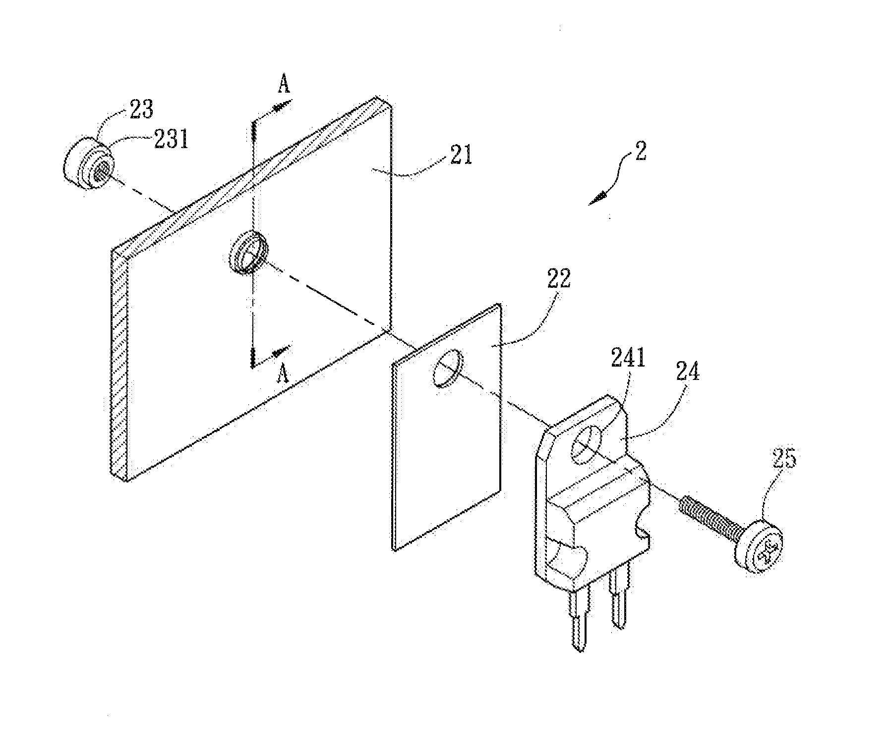
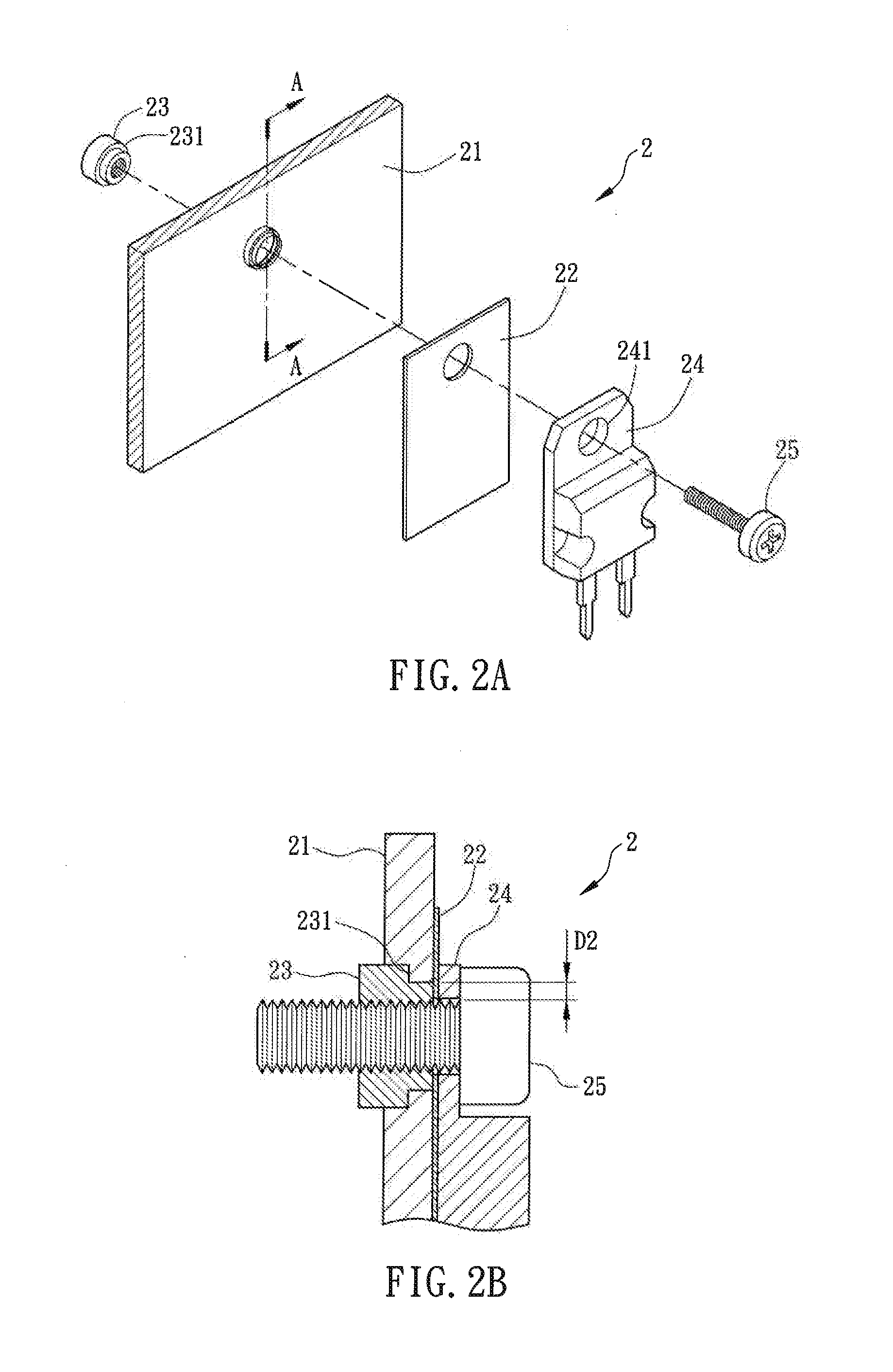
[0024]FIG. 2A is an exploded view of a heat dissipating structure 2 according to an embodiment of the invention, and FIG. 2B is a sectional view along a line A-A of the heat dissipating structure 2. The heat dissipating structure 2 can he applied to a power supplier or other electronic apparatuses. As shown in FIGS. 2A and 2B, the heat dissipating structure 2 includes a heat dissipating element 21, a first insulating element 22, a second insulating element 23, an electronic element 24, and at least a fixing element 25.

[0025]The heat dissipating element 21 can be a heat sink, a heat dissipating plate, or any component with heat dissipating function. The first insulating element 22 can be an insulating plate or any component with insulating function and is disposed at one side of the he...


PUM


Abstract

A heat dissipating structure includes a heat dissipating element, a first insulating element, a second insulating element, an electronic element and at least one fixing element. The first insulating element is disposed on one side of the heat dissipating element, while the second insulating element is disposed on another side of the heat dissipating element. The electronic element is disposed on the first insulating element. The fixing element fixes the electronic element on the heat dissipating element.

Description

CROSS REFERENCE TO RELATED APPLICATIONS[0001]This Non-provisional application claims priority under 35 U.S.C. §119(a) on Patent Application No(s). 101114454 filed in Taiwan, Republic of China on Apr. 24, 2012, the entire contents of which are hereby incorporated by reference.BACKGROUND OF THE INVENTION[0002]1. Field of Invention[0003]The present invention relates to a heat dissipating structure.[0004]2. Related Art[0005]Since various novel electronic apparatuses have more and more powerful functions and performances, the accompanying heat as the electronic apparatuses are operating is accordingly larger. In general, a heat dissipating structure is installed in an electronic apparatus for dissipating the generated heat.[0006]FIG. 1A is an exploded view of a conventional heat dissipating structure and FIG. 1B is a sectional view along a line A-A of the heat dissipating structure 1. As shown in FIGS. 1A and 1B, the conventional heat dissipating structure 1 includes a heat dissipating p...

Claims


Application Information

Patent Timeline
Patent Type & Authority Applications(United States)
IPC IPC(8): H05K7/20
CPCH05K7/2039H01L23/4006H01L2023/4062H01L2924/0002H01L2924/00
Inventor CHEN, HUNG-CHUAN
Owner DELTA ELECTRONICS INC
Why Eureka
Try Eureka