Flush Syringe Assembly With Controlled Pulsatile Flushing

a syringe and pulsatile technology, applied in the field of flushing syringe assemblies, can solve the problems of requiring expensive and potentially dangerous methods, partial or complete blockage of vad's, and occluded vad's, so as to increase and reduce the length of the plunger rod body

Active Publication Date: 2013-10-24
BECTON DICKINSON & CO
View PDF1 Cites 0 Cited by
  • Summary
  • Abstract
  • Description
  • Claims
  • Application Information

AI Technical Summary

Benefits of technology

[0015]In one or more embodiments, the thumb press includes a proximal end, a distal end, and a plurality of engagement tabs disposed at the distal end of the thumb press. The plunger rod of one or more embodiments may include a plurality of openings having a distal end, a proximal end and a length between the distal end and the proximal for receiving the engaging tabs. When the engagement tabs are engaged with the openings of the plunge rod, the engagement tabs may be configured to slide along the length of the plurality of openings as the compression force is applied to the thumb press in the distal direction and the compression force is released. Stated in other words, when the engagement tabs are engaged with the openings of the plunge rod, the engagement tabs may be configured to slide along the length of the plurality of openings as the a force is applied to the thumb press in the distal direction to cause the spring to compress and the same force is released. Therefore, in one or more embodiments, the expansion of the spring may also cause the engagement tabs to slide to the distal end of the plurality of openings and the compression of the spring allows the engagement tabs to slide to the proximal end of the plurality of openings.
[0020]In one or more embodiments, the compressible plunger rod body includes a telescoping segment attached to the proximal end of the plunger rod. The telescoping segment may be configured to slide in and out of the plunger rod body to reduce and increase the length of the plunger rod body. In such embodiments, the spring may be disposed between the telescoping segment and the plunger rod body. The spring may compress to generate a compression force as a force is applied to the plunger rod in the distal direction and expand as the compression force is released. In one or more embodiments, the expansion of the spring causes the telescoping segment to slide out of the plunger rod body to increase the length of the plunger rod body and the compression of the spring allows the telescoping segment to slide into the plunger rod body to reduce the length of the plunger rod body.
[0021]In one or more embodiments, the interaction of the plurality of projections with the protrusion of the barrel generates an engagement force that exerts a force on the plunger rod in a proximal direction. In such embodiments, increasing the compression force allows the plunger rod to overcome the engagement force and causes the plurality of projections to disengage from the protrusion. The disengagement of the plurality of projections and the protrusion causes the compression force to decrease.

Problems solved by technology

If not properly maintained, VAD's can become occluded.
Such build-up can cause partial or complete blockage of the fluid pathway in a catheter system and can also require expensive and potentially dangerous methods for purging the affected catheter or a total catheter exchange.
Often, such blockages lead to interruptions in therapy that may compromise patient care.
The build-up of residue within a catheter can also increase infection risk by providing a breeding medium for microorganisms.
When such techniques are used in conjunction with catheters, turbulence is introduced within the catheter.
However, the use of features that provide the force differential that creates pulsing fluid flow generally cannot be applied with infusion pumps or other delivery systems that require slow and controlled delivery of medication to patients.
In addition, push-pulse techniques and flush syringes that provide push-pulse techniques often do not provide a way to control the increases in pressure within the flush syringe.
These pressure levels within the barrel can lead to overpressurizing catheters or other VADs that can also lead to interruptions in therapy that may compromise patient care.
Further, high pressures within the barrel during flushing can also lead to vein blowout.

Method used


Image

  • Flush Syringe Assembly With Controlled Pulsatile Flushing
  • Flush Syringe Assembly With Controlled Pulsatile Flushing
  • Flush Syringe Assembly With Controlled Pulsatile Flushing

Examples


Embodiment Construction

[0045]Before describing several exemplary embodiments of the invention, it is to be understood that the invention is not limited to the details of construction or process steps set forth in the following description. The invention is capable of other embodiments and of being practiced or being carried out in various ways.

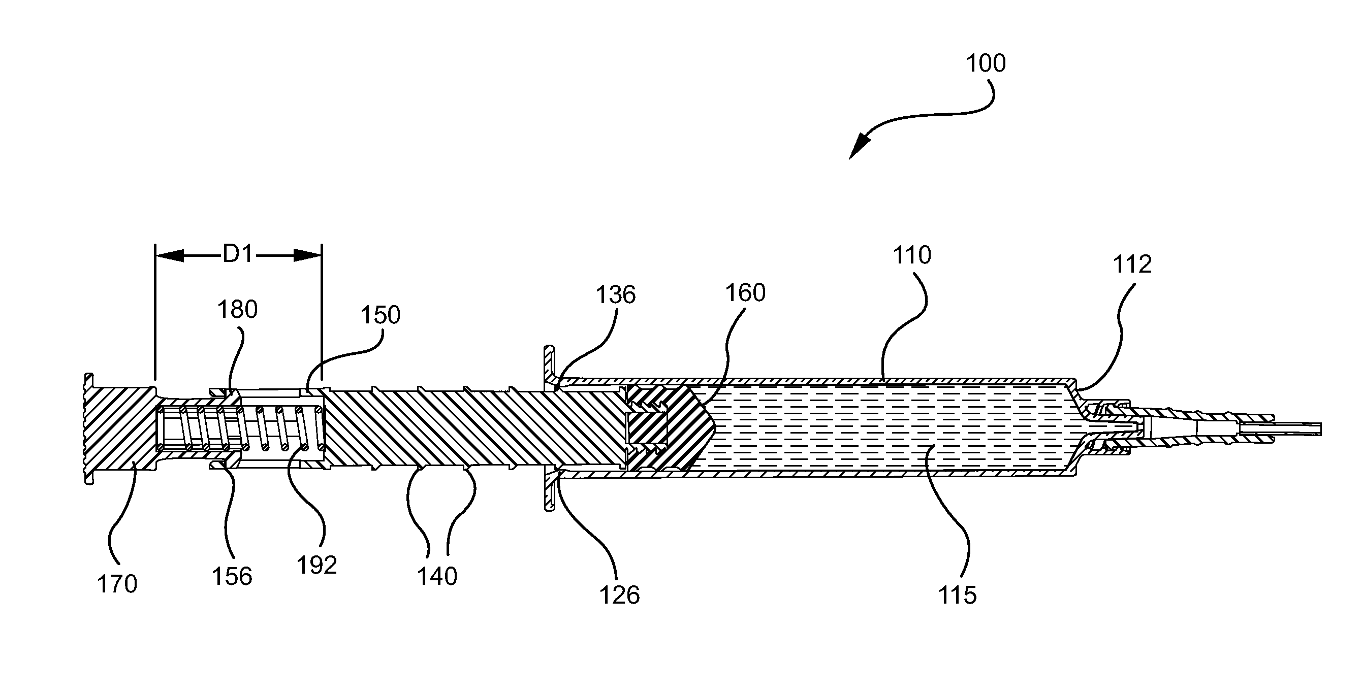
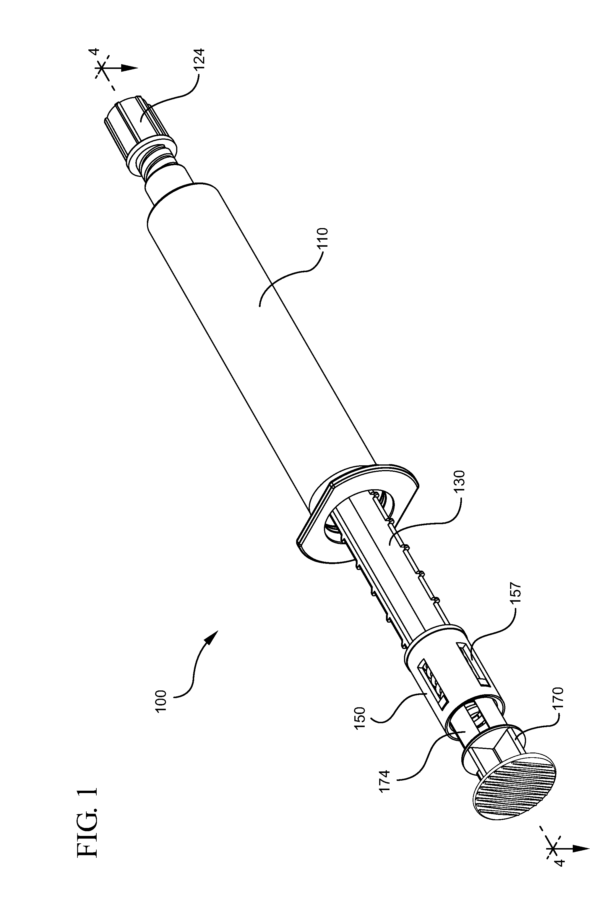
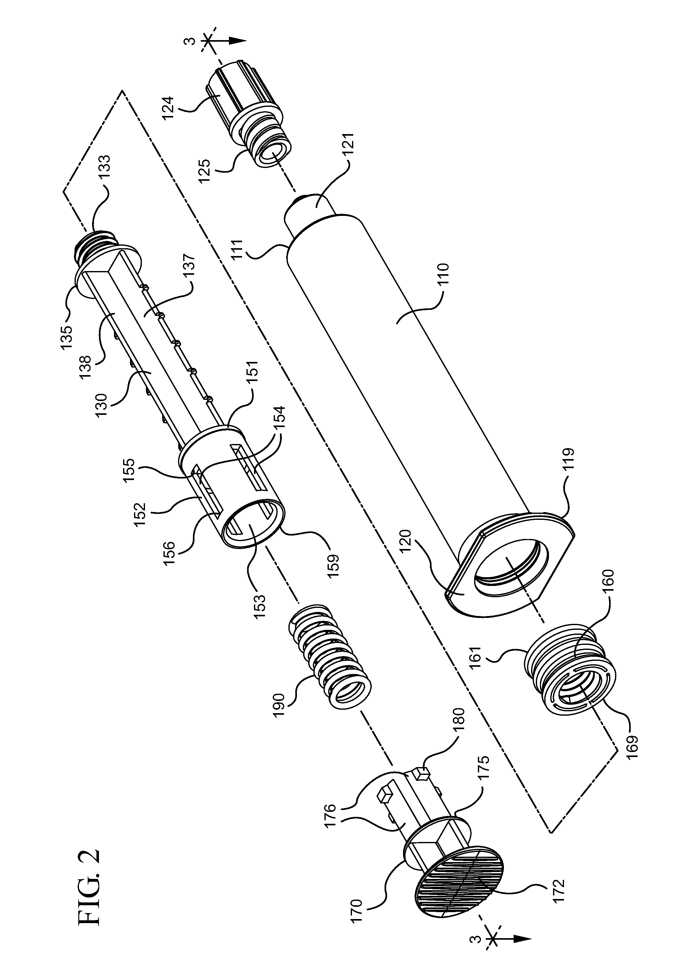
[0046]A first aspect of the present invention pertains to a flush syringe assembly configured to permit pulsatile movement of the plunger rod. The pulsatile movement of the plunger rod imparts pulsing flow to the flush solution as it is expelled. The first aspect of the present invention also includes flush syringe assemblies with a pulse control element to control the pressure of the flush solution being expelled by the flush syringe assembly. A flush syringe assembly 100 according to an embodiment of the first aspect of the present invention is shown in FIGS. 1-16.

[0047]FIG. 1 shows the flush syringe assembly 100 in an assembled state. The flush syringe assembly 1...


PUM


Abstract

Flush syringe assemblies capable of creating pulsatile movement of the plunger rod as it moves in the distal direction within a syringe barrel, while preventing overpressurization of the cathether are provided. An exemplary flush syringe assembly includes a syringe barrel with a first pulsing element and a chamber with flush solution, a plunger rod with a stopper and a second pulsing element that interacts with the first pulsing element to provide an engagement force that causes pulsatile movement of the plunger rod and a thumb press slidably attached to the plunger rod with a pulse control element. The pulse control element is compressible to create a compression force that is greater than the engagement force of the first pulsing element and the second pulsing element.

Description

CROSS-REFERENCE TO RELATED APPLICATIONS[0001]This application is a continuation of U.S. patent application Ser. No. 12 / 833,551, filed Jul. 9, 2010 which claims the benefit of priority from U.S. Provisional Application No. 61 / 224,688, filed Jul. 9, 2009, the disclosures of which are hereby incorporated in their entirety by reference thereto.TECHNICAL FIELD[0002]Aspects of the present invention relate to flush syringe assemblies that provide controlled pulsatile flushing of catheters and other vascular accessing devices (VADs) and methods of flushing a catheter.BACKGROUND[0003]VAD's are commonly used therapeutic devices and include IV catheters. There are two general classifications of VAD's, peripheral catheters and central venous catheters. If not properly maintained, VAD's can become occluded. To ensure VAD's are used properly and do not become occluded, standards of practice have been developed. These standards include a cleaning procedure, which is commonly referred to as a flush...

Claims


Application Information

Patent Timeline
Patent Type & Authority Applications(United States)
IPC IPC(8): A61M5/315
CPCA61M5/31501A61M5/31511A61M5/31595A61M2025/0019A61M2206/10A61M5/31505A61M5/3129A61M2005/3143A61M2005/31508A61M2005/3151
Inventor KOSINSKI, ANTHONY J.TEKESTE, GIRUM YEMANECHARLES, NICHOLA
Owner BECTON DICKINSON & CO
Why Eureka
Try Eureka