Tensioning unit

a technology of tensioning unit and spring element, which is applied in the direction of connection, basic electric element, belt/chain/gearing, etc., can solve the problems of over-tensioning or too little tensioning of pull elements, and achieve the effect of reducing the length of the spring elemen

Active Publication Date: 2019-07-02
IDEEMATEC DEUTSCHLAND GMBH
View PDF19 Cites 0 Cited by
  • Summary
  • Abstract
  • Description
  • Claims
  • Application Information

AI Technical Summary

Benefits of technology

[0005]This configuration advantageously makes it possible for one or two pull elements, which are connected to or via the tensioning unit, to be tensioned or re-tensioned, wherein a basic tensioning is provided via the spring element in a mounting state. In this case, mounting state designates a basic state of the tensioning unit, that is to say the state, in which the tensioning unit is mounted for example (in a cable arrangement or the like), but does not “operate” further, in the sense that it provides length compensation for example. The spring element has a length, which can be shortened. Thus, a certain yield can be provided by the spring element, in the event that the pull element(s) are additionally tensioned. By contrast, in the mounting state, the length of the tensioning element is shortened in such a manner that the pretensioning is built up, which pretensioning is designed to increase the length of the tensioning element. As a result, it is possible to advantageously react to one or both of the previously mentioned tensioning element lengthening. This expediently takes place via the pretensioning or via the length enlargement thereby possible, which is directed away from the spring element.
[0007]In a preferred embodiment, the arrangement is such that a first pull element is connected to the spring element in such a manner that the same is compressed or shortened if the first pull element is loaded with tension. The tensile force of the pull element is converted to a compressive tension at the tensioning unit. The length of the spring element is consequently reduced. A second pull element is advantageously connected to the tensioning unit in such a manner that the length of the spring element can likewise be reduced if a tensile force acts on the second pull element. In this case also, the tensile force of the pull element is converted to a compressive force. The pull elements are therefore attached in such a manner that tensile stresses or tensile forces on the pull elements act as compressive forces on the tensioning unit and therefore on the tensioning element and the spring element. The spring element can therefore be compressed or the length thereof can be shortened by means of a tensile stress both on the first and on the second pull element. This is enabled by means of the position of the force introduction regions, which is described more precisely in the following. Basically, one of the pull elements or if necessary also a fixed point is connected to the tensioning unit in such a manner that the pull element conducts its force “directly” to the spring element, whilst the other pull element or if appropriate a fixed point conducts the force thereof to the spring element via the tensioning element and / or a boundary element, which is explained further in the following. The word “directly” is only to be understood to mean that no tensioning element is arranged between the spring element and the pull element. The tensioning element is preferably designed to increase and to reduce the length thereof. This makes it possible for the pull elements to be re-tensioned. To this end, the tensioning element advantageously has the pretensioning in the mounting state, which is designed to increase the length of the tensioning element.
[0013]The spring element is preferably a compression spring. In a preferred embodiment, the spring element is formed by one or a plurality of disc springs, particularly by a packet of disc springs. A disc spring is understood to mean a conical annular bowl, which can be loaded in the axial direction. The force introduction and transmission advantageously takes place along the inner edges of the disc springs. A packet or a column of disc springs is advantageously used. In this case, the individual disc springs can advantageously be connected in series or in parallel. In a particularly preferred embodiment, the packet or the column of disc springs is formed by ten disc springs, which are connected in series. Disc springs of DIN 2093 type, which have an internal diameter of approximately 12 mm, and external diameter of approximately 34 mm and a wall thickness of approximately 1.5 mm, are advantageously used. Likewise, the packet can also be formed by disc springs of different types, that is to say by disc springs which have different spring forces. Likewise, the use of a single disc spring is also possible. Alternatively, an elastomer or a packet or a series of elastomers or the like can also be used instead of a packet of disc springs or one disc spring. Likewise, a coil spring could be used, which is then advantageously provided with a corresponding run-out or length limit, which prevents a forbidden length enlargement of the spring element.
[0023]The tensioning unit expediently comprises an external transmission element, which is arranged outside the spring element and the tensioning element, wherein the inner transmission element can be moved relatively to the outer transmission element, namely via the spring element and / or the tensioning element. Preferably, the external transmission element is bent e.g. from a metal sheet. Ultimately, the external transmission element is used to start the force introduction or introduce the retaining or tensile force of a pull element or a fixed point, such as e.g. a fixed body, into the spring element. In this case, the shape of the external transmission element enables the conversion of a tensile force of a pull element connected thereto into a compressive force, which can compress or shorten the spring element. By contrast, the inner transmission element is used to introduce the force of a further pull element or a fixed point so to say from the interior, via the tensioning element, into the spring element. The position and shape of the inner transmission element allow the tensile force of the pull element connected thereto to be converted into a compressive force, which can compress or shorten the spring element or also the tensioning element. Ultimately, this arrangement also makes it possible for the pretensioning of the tensioning element to tension both pull elements (if the tensioning unit is connected to two pull elements).

Problems solved by technology

It is problematic in this case, however, that the pull elements can only fulfil their object if they have a corresponding tension, which must be neither too low nor too high.
The tension of the pull elements can vary however for example due to weather influences or construction-determined influences, particularly when moving the tracking devices, so that there is the risk that the pull elements are either over-tensioned or have too little tensioning.

Method used


Image

  • Tensioning unit
  • Tensioning unit
  • Tensioning unit

Examples


Embodiment Construction

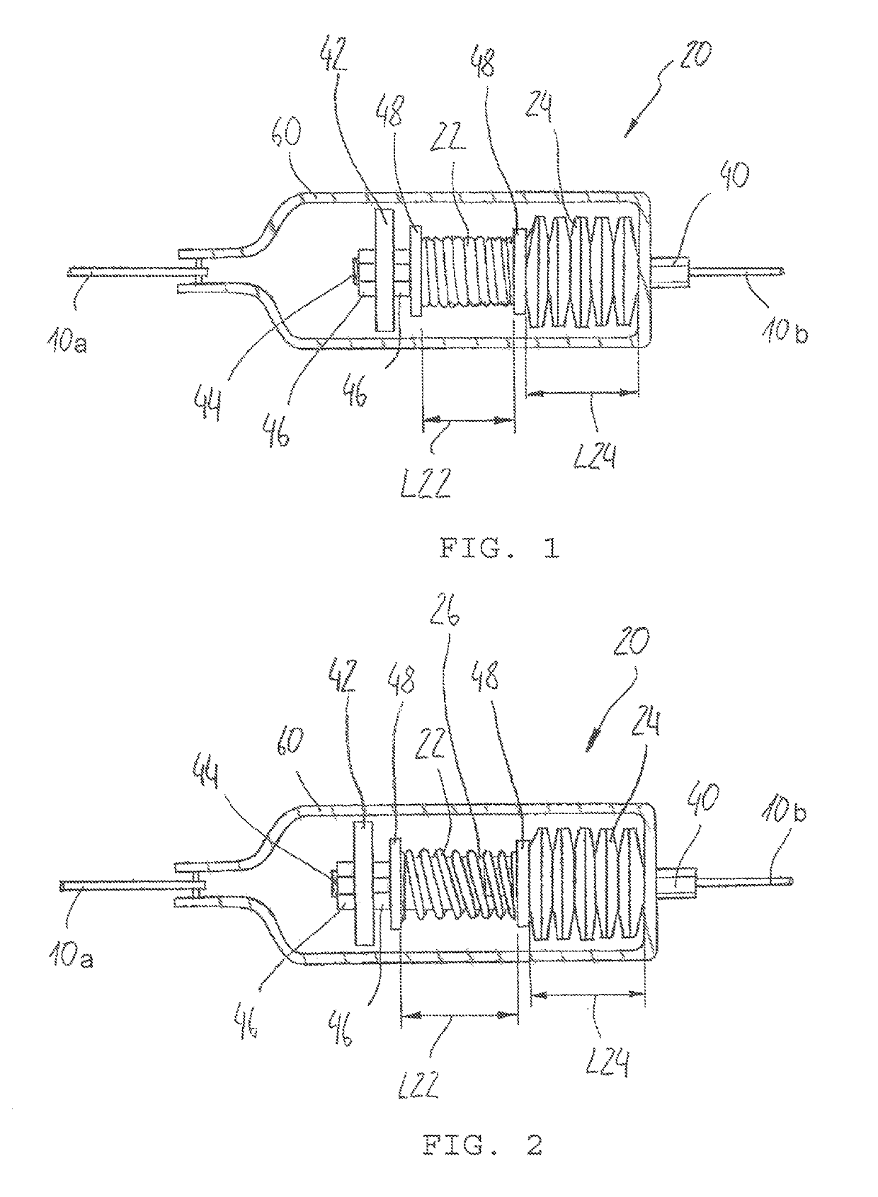
[0033]FIG. 1 shows a tensioning unit 20, which is arranged between two pull elements 10a, 10b. The left pull element 10a is arranged on a spring element 24 via an external transmission element 60, which is of essentially bow-shaped construction. The spring element 24 consists of ten disc springs in a series connection. A tensioning element 22 is arranged next to the spring element 24 or in series with the same. The tensioning element 22 is in turn arranged between two intermediate washers 48. The tensioning element 22 is constructed as a coil spring and maximally pretensioned in a mounting state shown in FIG. 1. In this state, it has a length L22, which is measured between the two intermediate washers 48. Arranged within the tensioning element 22 is a boundary element, which cannot be seen inFIG. 1, however, as the tensioning element 22 or the coil spring is completely pretensioned and the windings make it impossible to see “inside”. Nuts 46 are provided in order to apply e.g. the p...


PUM


Abstract

A tensioning unit for pull elements such as cables includes a tensioning element and a spring element, wherein the tensioning element and the spring element are arranged in a row, a length of the tensioning element is shortened in such a manner that the tensioning element has a pretension, the pretension is designed to increase the length of the tensioning element, and wherein the direction of the length enlargement of the tensioning element is directed away from the spring element.

Description

BACKGROUND OF THE INVENTION[0001]The present invention relates to a tensioning unit, particularly for pull elements such as cables, and a cable arrangement.[0002]The present invention is used for example in the field of solar module technology and in the field of tracking devices for solar modules in particular. Pull elements or ties, such as ropes and cables, for example made from wire, are used here for pivoting the solar modules and the solar module tables. Furthermore, they are used if e.g. (support) structures or arrangements have to be tensioned or stiffened. It is problematic in this case, however, that the pull elements can only fulfil their object if they have a corresponding tension, which must be neither too low nor too high. The tension of the pull elements can vary however for example due to weather influences or construction-determined influences, particularly when moving the tracking devices, so that there is the risk that the pull elements are either over-tensioned o...

Claims


Application Information

Patent Timeline
Patent Type & Authority Patents(United States)
IPC IPC(8): F16G11/12
CPCF16G11/12Y10T403/32819
Inventor KUFNER, JOHANN
Owner IDEEMATEC DEUTSCHLAND GMBH
Why Eureka
Try Eureka