
Apparatus for controlling injection pressure in offshore enhanced oil recovery

a technology of injection pressure and apparatus, which is applied in the direction of drilling casings, well accessories, drilling pipes, etc., can solve the problems of gels not being injected into formations without damage, water-soluble polymers are difficult to disperse, and the use of large oilfields is subject to certain technical problems, so as to achieve the effect of simple system, robustness and simplicity

Active Publication Date: 2016-05-03
S P C M SA
View PDF15 Cites 0 Cited by
  • Summary
  • Abstract
  • Description
  • Claims
  • Application Information

AI Technical Summary

Benefits of technology

[0018]The objective of the invention is therefore to simplify the system so as to give it the robustness and simplicity needed for subsea use.
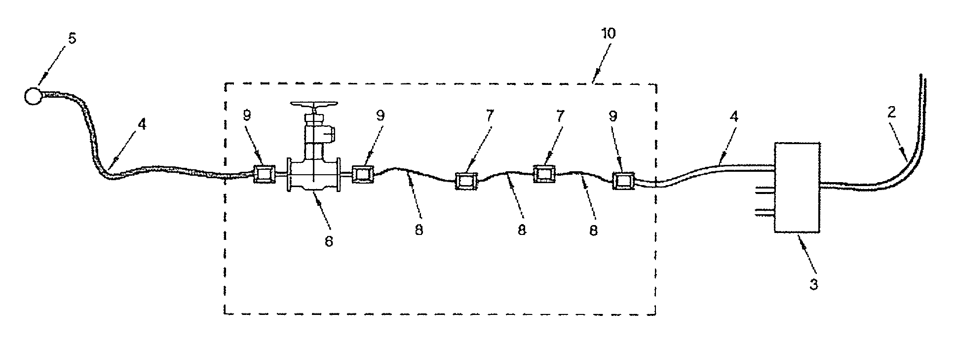
[0023]The invention consists in inserting, upstream or downstream of a choke, a pressure reducer in the form of a tube that makes it possible to absorb most of the pressure drop needed, the choke itself making it possible to adjust the pressure within the range between 0 and 10 bar, that is to say over a range that does not cause significant degradation of the polymer.
[0024]The combination of a pressure reducer, the dimensions of which may be calculated on the ground, with a choke, the role of which is to adjust the pressure without significantly degrading the polymer, makes it possible to solve the problem stated above. This makes it possible to limit the degradation of the polymer in a completely acceptable manner by reducing it to less than 10%. For example, on a well where the pressure reduction needed is of the order of 50 bar, the pressure reducer makes it possible to obtain a pressure drop of around 45 bar and the choke from 0 to 10 bar.
[0029]In one preferred embodiment, the tube of the pressure reducer comprises at least one flexible tube section, which makes it possible to be able to manipulate the tube more easily in an underwater environment during the installation thereof or maintenance thereof by divers or underwater robots.
[0047]In the process according to the invention, the pressure control may be carried out owing to the opening or closing of the choke controlled remotely from the platform or FPSO boat. It may also be carried out by increasing or reducing the length of the tube by the addition or removal of a tube section, owing to the intervention of divers or underwater robots. This handling is even easier because the tube section or sections are flexible and because quick couplings are used.

Problems solved by technology

However, its use in large oilfields comes up against certain technical problems which are gradually being solved.
These types of water-soluble polymers are very difficult to disperse due to a bonding and agglomerating effect that gives gels or “fish eyes” that take a long time to dissolve.
These gels cannot be injected into the formations without damage.
The second problem is the mechanical degradation of the polymer.
This system requires numerous pumps (one per well) and numerous pipelines, which increases the cost of the installation.Another solution is to create a solution at the final concentration (500 to 3000 ppm) and to inject it into each well by means of a linear pressure reducer as described in U.S. Pat. No. 8,607,869.
But this type of apparatus becomes very complex when it is desired to adapt it to subsea applications, in particular as regards the replacement of valves, of coils, of measurement apparatus, the inspection of the valve openings, the connections to the surface and the high maintenance, depending on the case, by divers or robots.
Extrapolated to a subsea installation, this type of apparatus leads to additional constraints inherent to its technology (control and measuring devices, confirmation of the openings of the valves, measurement of flow rate and pressure, modules that can be disconnected for maintenance, electrical housings, umbilicals, etc.).

Method used


Image

  • Apparatus for controlling injection pressure in offshore enhanced oil recovery
  • Apparatus for controlling injection pressure in offshore enhanced oil recovery
  • Apparatus for controlling injection pressure in offshore enhanced oil recovery

Examples


Embodiment Construction

Installation Example

[0056]FIG. 4 represents a conventional offshore secondary oil recovery installation. It comprises a floating production, storage and offloading (FPSO) unit. The platform is equipped with tubes (riser) (2) into which the polymer solution is injected by means of the main injection pump. Each tube is intended to supply a manifold or distributor (3) from which as many tubes (4) as wells (5) spread out. The diameter of the tube supplying the manifold is the same as that of the tubes (4) leaving the manifold. In practice, the diameter is of the order of 10 inches. In this prior art installation, the decrease in pressure at each well (5) is obtained by installing a choke (6), in each line (4). As explained above, these chokes, by decreasing the pressure, do not present a problem for injections of water only but degrade the polymer when an aqueous polymer solution is injected.

[0057]In order to overcome this drawback and as represented in FIG. 5, the invention consists in...


PUM


Abstract

An apparatus for controlling the injection pressure of an aqueous polymer solution in a subsea oil wellhead, includes a linear pressure reducer in the form of a tube connected in series to the main injection line that is capable of absorbing the majority of the pressure drop and a choke that is capable of being regulated in order to enable a pressure control between 0 and 10 bar. Also, a process of offshore enhanced oil recovery by injection of an aqueous polymer solution uses the apparatus.

Description

FIELD OF THE INVENTION[0001]The present invention concerns offshore enhanced oil recovery by injection of an aqueous polymer solution.BACKGROUND OF THE INVENTION[0002]Enhanced oil recovery (EOR) which was industrialized particularly in the United States between 1973, the date of the first oil crisis, and 1986, the date of the oil price collapse to 10 dollars a barrel, was put back on the agenda at the beginning of the 2000s decade when the price of oil exceeded 40 dollars a barrel. With a current cost of 100 dollars a barrel, enhanced oil recovery with the use of water-soluble polymers, which permits an additional 10% to 20% increase of the yield of the reserves in place, has become a choice technique.[0003]However, its use in large oilfields comes up against certain technical problems which are gradually being solved.[0004]One of the device that has enabled this development is the PSU (Polymer Slicing Unit) described in patent EP 2 203 245. These types of water-soluble polymers are...

Claims


Application Information

Patent Timeline
Patent Type & Authority Patents(United States)
IPC IPC(8): E21B34/04E21B43/01E21B17/20E21B19/00E21B43/16E21B43/20
CPCE21B43/20E21B43/01E21B17/20E21B19/002E21B34/04E21B43/16E21B43/12E21B43/121E21B43/162
Inventor REMY, PASCALPICH, EMMANUEL
Owner S P C M SA
Learn More