Capacitance fluid volume measurement

a technology of capacitance fluid and volume measurement, which is applied in the field of capacitance fluid volume measurement, can solve the problems of toxic end products of nitrogen metabolism (urea, creatinine, uric acid, etc.) and the inability to balance water, minerals and the excretion of daily metabolic load,

Inactive Publication Date: 2006-09-19
BAXTER INT INC +1
View PDF40 Cites 130 Cited by
  • Summary
  • Abstract
  • Description
  • Claims
  • Application Information

AI Technical Summary

Benefits of technology

[0058]It is therefore an advantage of the present invention to provide an improved medical fluid volume measurement system.
[0059]Another advantage of the present invention to provide an improved system for providing dialysis treatment.
[0060]An advantage of the present invention is to provide volume measurement systems and methods for use in continuous flow peritoneal dialysis treatment.
[0061]Another advantage of the present invention is to provide improved methods of measuring medical fluid volumes.
[0062]A further advantage of the present invention is to provide non-invasive fluid volume measurement.
[0063]Still another advantage of the present invention is to provide capacitance fluid sensing and fluid volume measurement devices and methods.

Problems solved by technology

Due to disease, insult or other causes, a person's renal system can fail.
The balance of water, minerals and the excretion of daily metabolic load is no longer possible in renal failure.
During renal failure, toxic end products of nitrogen metabolism (urea, creatinine, uric acid, and others) can accumulate in blood and tissues.
Errors in the amount of fluid exchanged can occur when relying on manual fluid exchanges.
As a consequence, known CFPD dialysis treatments require a large amount of fresh dialysate, which must be tracked or calculated.
Accordingly, the measurement of the amount of fluid pumped may be inaccurate, for example, less fluid may be actually pumped than the amount calculated.
These drawbacks can become more pronounced over many pump strokes, such as when a smaller pump requires numerous pump strokes to fill or empty the peritoneal cavity.
The accuracy of measuring fluid volume pumped can become more difficult when the size of the pump chamber is small and the pump is operated through many pump strokes.

Method used


Image

  • Capacitance fluid volume measurement
  • Capacitance fluid volume measurement
  • Capacitance fluid volume measurement

Examples


Embodiment Construction

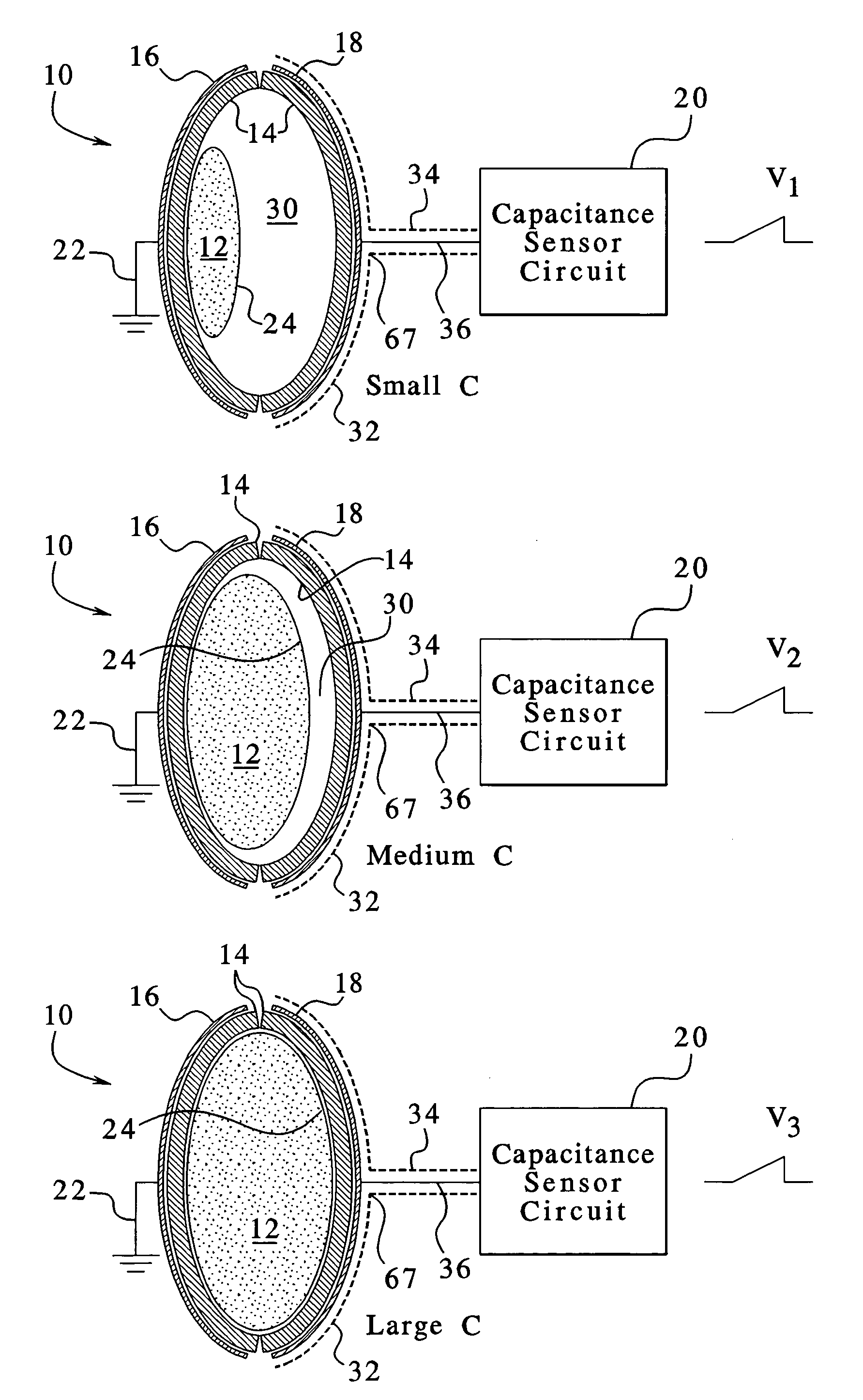
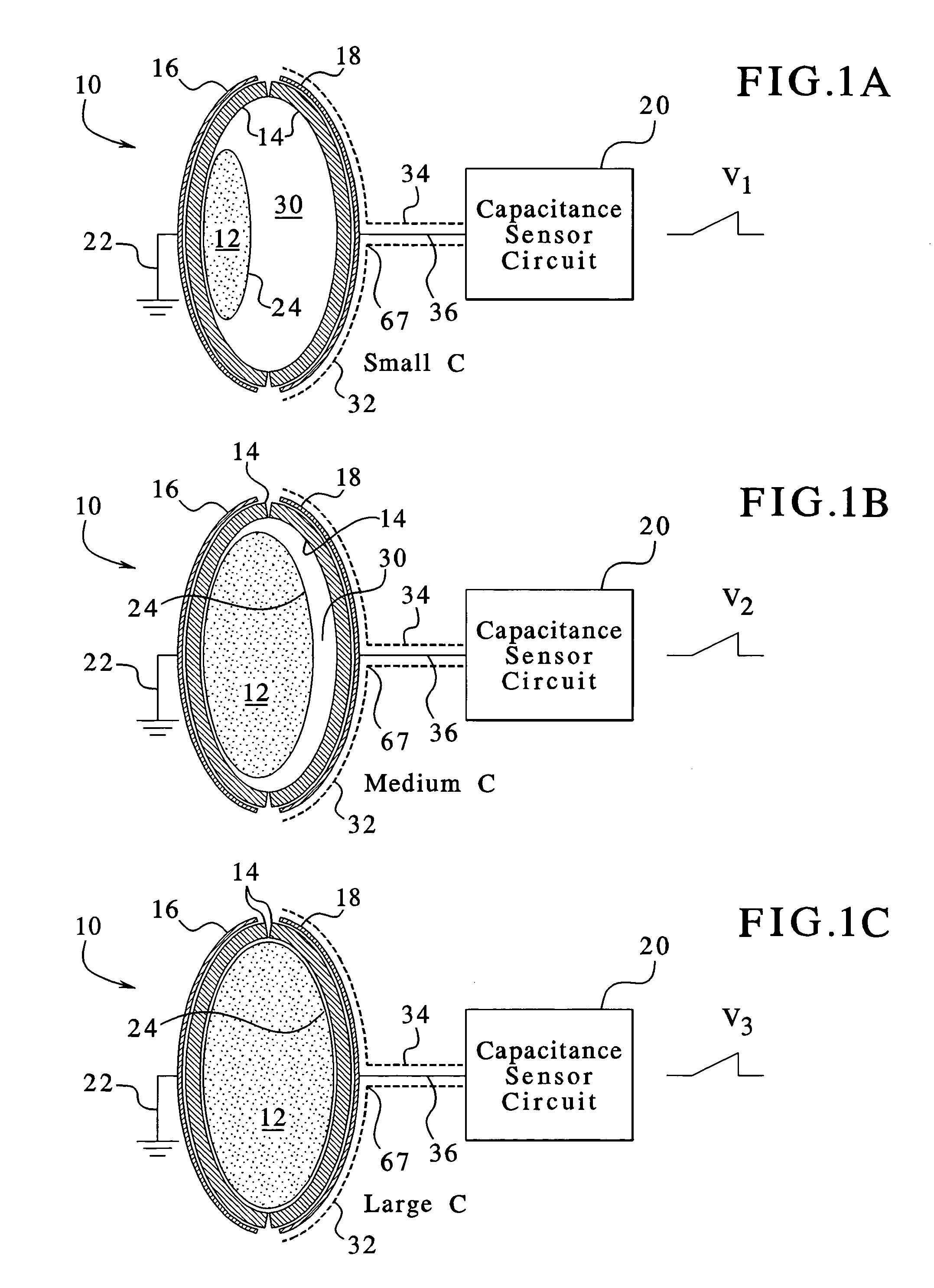
[0075]The present invention provides medical fluid volume sensors, systems for performing medical treatments using the medical fluid volume sensors, and methods pertaining to same. The present invention particularly provides fluid volume sensors, systems and methods that can be used for peritoneal dialysis treatment and with peritoneal dialysis systems. One such peritoneal dialysis system is a continuous flow peritoneal dialysis system which continuously and simultaneously infuses and drains dialysate to and from a patient's peritoneal cavity. The peritoneal dialysis system, and thus the present invention, can be connected to a dual lumen catheter implanted in the peritoneal cavity, or other multi-lumen patient access, for example.

[0076]It should be noted, however, that the present invention can be used for a variety of medical treatments as well as a variety of dialysis systems and methods. For example, the present invention can be used in hemodialysis. Likewise, the principles and...


PUM


Abstract

A fluid volumetric pumping system has a fluid pump and capacitor plates disposed around a pump chamber of the fluid pump. The capacitance between the capacitor plates changes as the volume of fluid in the pump chamber changes. An electrical circuit measures a change in the capacitance between the plates and outputs a signal indicative of the volume of fluid in the pump chamber. The pump having the capacitance sensor of the present invention fluidly connects to a patient. In an embodiment, a peritoneal dialysis system provides dialysate to the patient via the pump, and the capacitance sensor measures the volume of dialysate supplied to and drained from a peritoneal cavity of the patient.

Description

BACKGROUND OF THE INVENTION[0001]The present invention generally relates to devices that sense fluid and measure volumes of fluid. More specifically, the present invention relates to sensors that measure fluid volumes, preferably medical fluids, for example, fluids used during dialysis therapy.[0002]Due to disease, insult or other causes, a person's renal system can fail. In renal failure of any cause, there are several physiological derangements. The balance of water, minerals and the excretion of daily metabolic load is no longer possible in renal failure. During renal failure, toxic end products of nitrogen metabolism (urea, creatinine, uric acid, and others) can accumulate in blood and tissues.[0003]Kidney failure and reduced kidney function have been treated with dialysis. Dialysis removes waste, toxins and excess water from the body that would otherwise have been removed by normal functioning kidneys. Dialysis treatment for replacement of kidney functions is critical to many p...

Claims


Application Information

Patent Timeline
Patent Type & Authority Patents(United States)
IPC IPC(8): G01F23/26A61M1/16A61M5/145A61M5/168
CPCA61M1/1658A61M5/14216A61M5/14224G01F23/263A61M5/16831A61M2205/3317A61M2205/3379A61M1/28A61M1/287A61M1/284A61M1/155A61M1/154A61M1/159A61M1/1524A61M1/1561
Inventor LAUMAN, BRIANHOPPING, PETEKIENMAN, RICKDIN, SHAHIDCHILDERS, ROBERT W.
Owner BAXTER INT INC
Why Eureka
Try Eureka