Extension -mode angular velocity sensor

a technology of angular rate sensor and extension mode, which is applied in the direction of acceleration measurement using interia force, turn-sensitive devices, instruments, etc., can solve the problems of reducing the cost of the sensor. , the effect of simplifying the sensor

Active Publication Date: 2011-03-17
INVENSENSE
View PDF76 Cites 122 Cited by
  • Summary
  • Abstract
  • Description
  • Claims
  • Application Information

AI Technical Summary

Benefits of technology

[0008]An angular rate sensor of the present inventions includes a drive system based on an extension vibratory mechanical mode. This mode provides a simpler system, reducing costs of...

Problems solved by technology

One problem with this type of sensor is the duplication of driving system and drive electronics.
These prior devices are all limited in various ways and n...

Method used


Image

  • Extension -mode angular velocity sensor
  • Extension -mode angular velocity sensor
  • Extension -mode angular velocity sensor

Examples


first embodiment

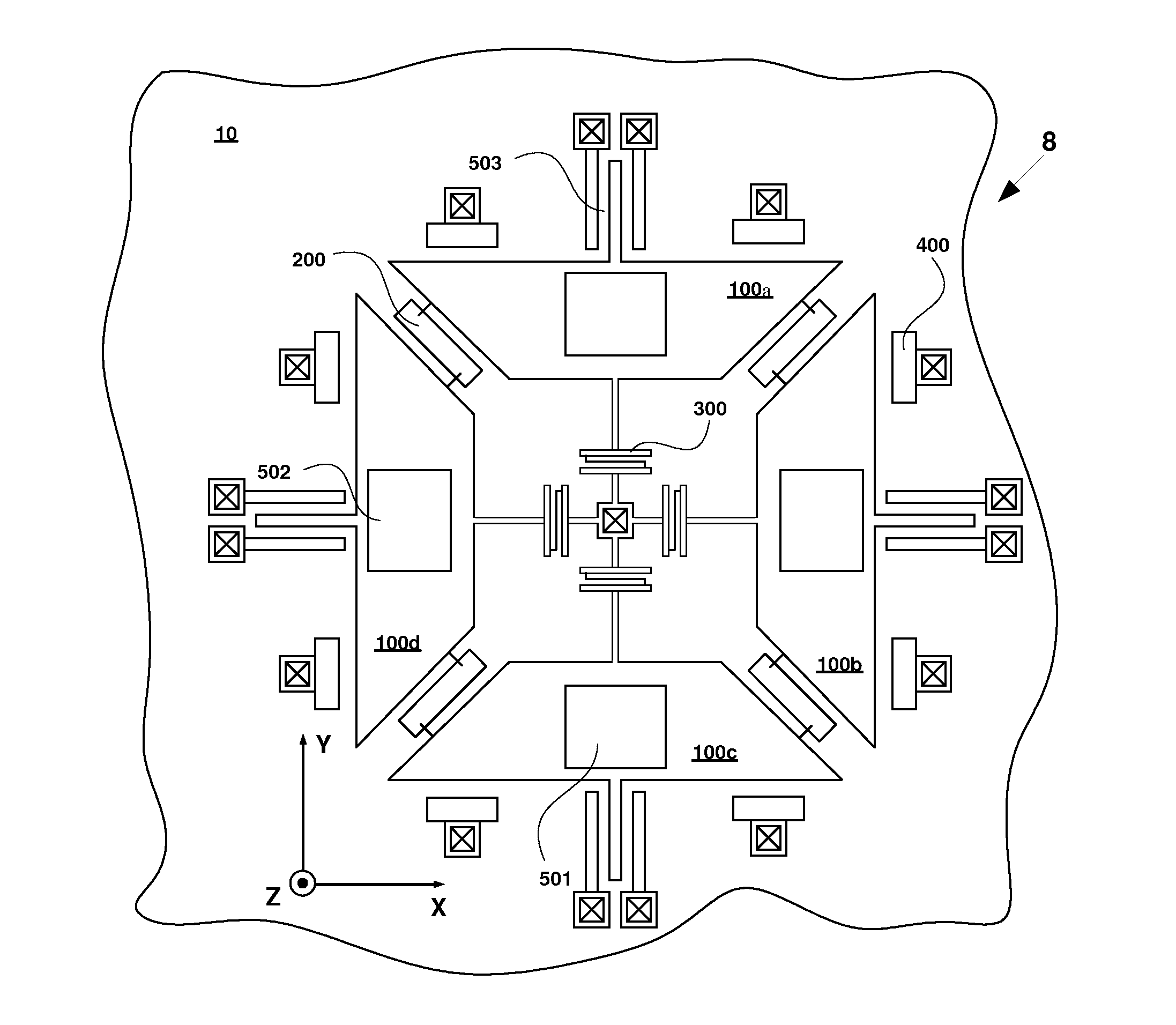
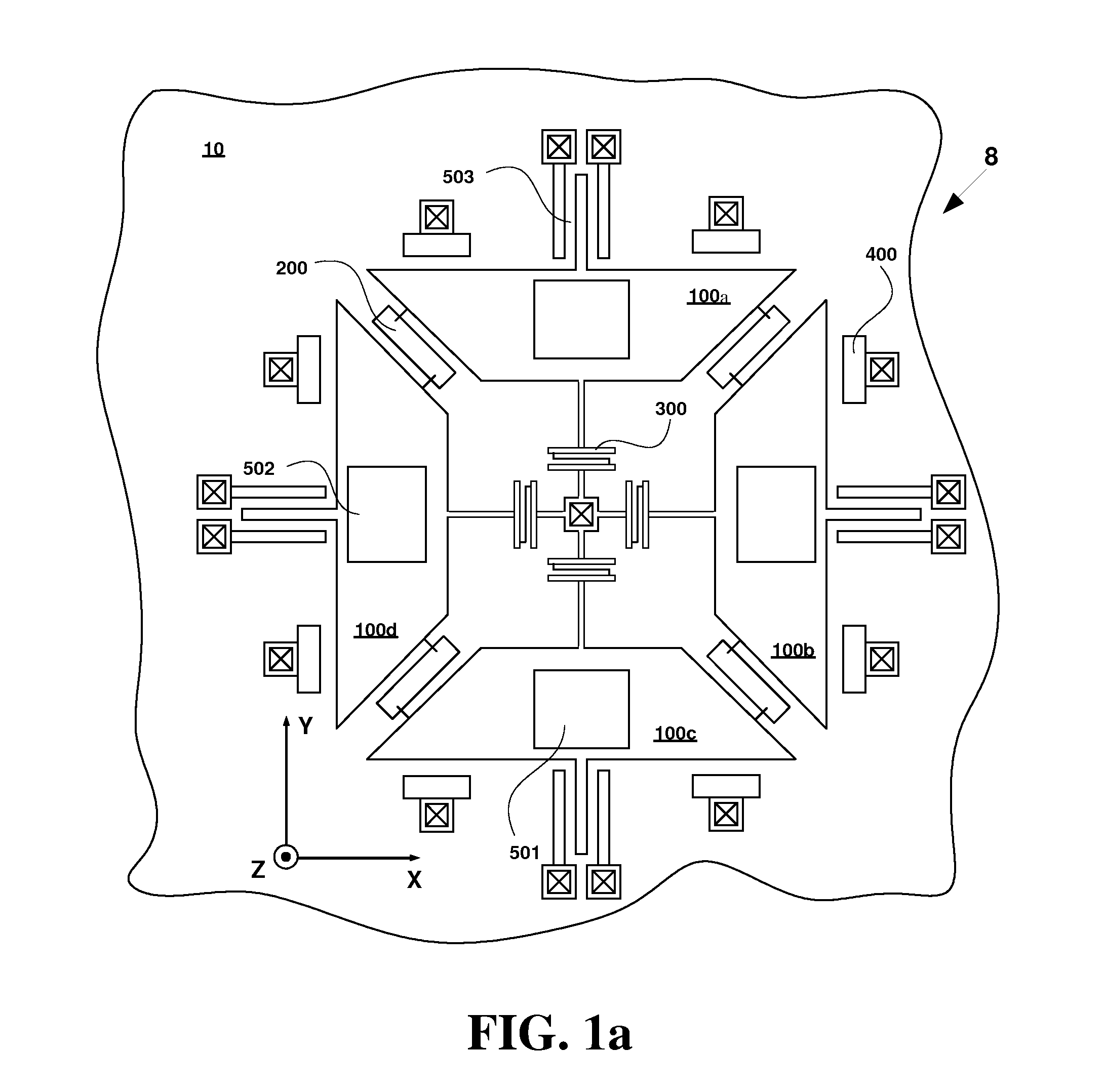
[0028]Referring to FIG. 1a, an angular rate sensor 8 of the present invention is disclosed. The angular rate sensor 8 may sense a rate of rotation of the sensor 8, i.e. angular velocity, about at least one of three input axes. In the described example, the X axis may be a first input axis, the Y axis may be a second input axis, and a Z axis may be a third input axis.

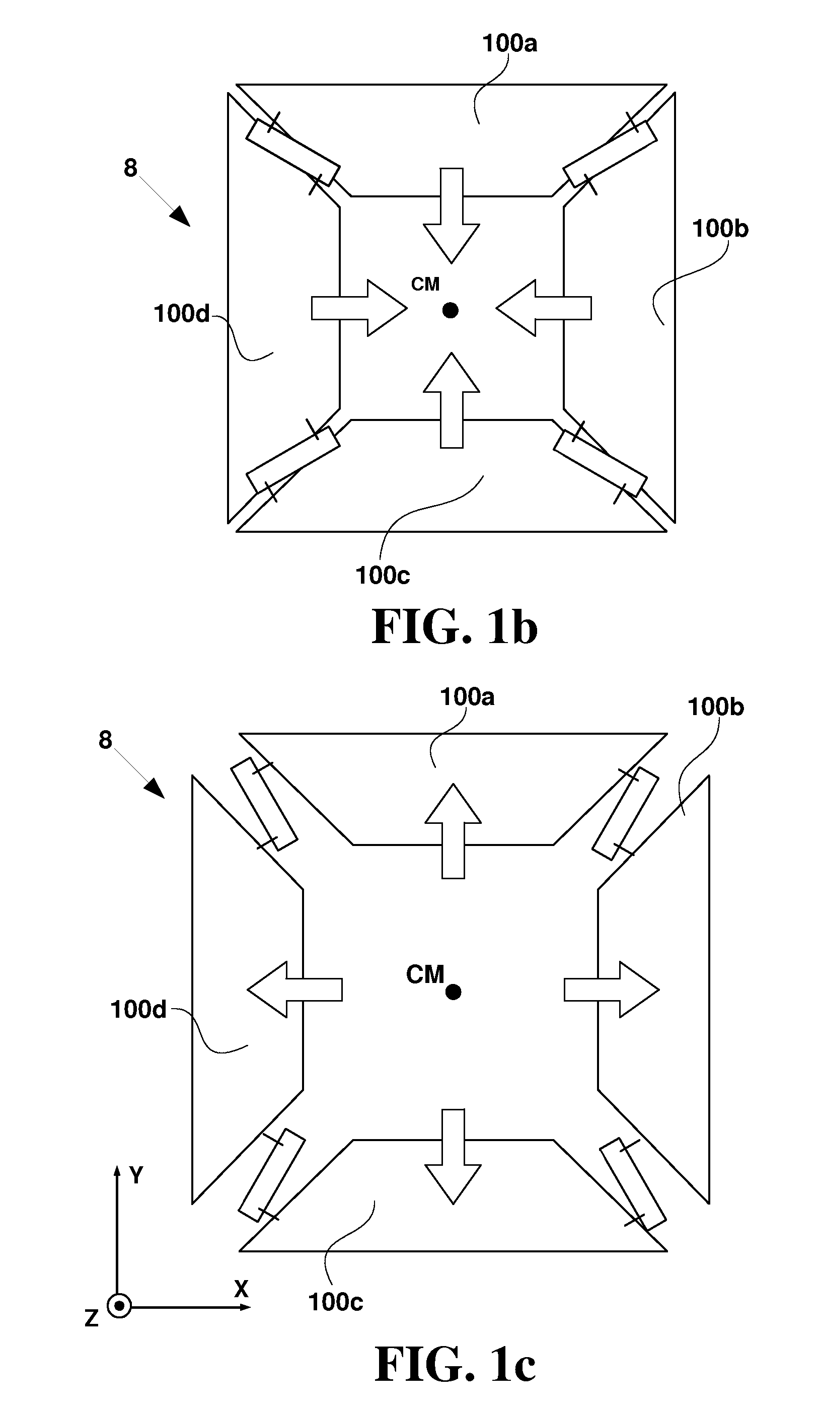
[0029]The angular rate sensor 8 includes a base 10 and a plurality of proof masses 100, indicated specifically in FIG. 1a as masses 100a-d, disposed within a plane parallel to the base. The plane parallel to the base and defined by the masses 100a-d, i.e. the X-Y plane extending through the center of the masses 100, is referred to herein as the “mass plane.” The proof masses 100a-d in the described embodiment are multiple discrete masses and are shown to form a rectangle or square shape when viewed as in FIG. 1a, but may be other shapes in other embodiments (e.g., as in FIG. 2a described below). In some embodiments the m...

embodiment 18

[0042]Referring to FIG. 4a, the angular rate sensor shows the use of a frame 250. Approximately circular proof masses 100a-d are used as an example. In this embodiment, the linkage 200 may comprise the linkage portions 210a-d and further comprise a substantially planar frame 250 that encircles or surrounds the masses 100a-100d within the mass plane, i.e. the outsides of the masses within the mass plane are surrounded by the frame 250. Furthermore, the linkage 200 may include frame flexures 280a-d. Four frame flexures 280a-d are shown in the described embodiment of FIG. 4a, but other embodiments can provide different numbers of flame flexures. At least one of the masses 100a-d may be flexibly coupled to the frame through a frame flexure 280.

[0043]In one implementation, each of the flexures 280a-d may be substantially compliant in a direction along the axes radiating from the center of the mass CM within the mass plane, and may be substantially stiff in both the axis normal to the mas...

embodiment 26

[0054]Referring to FIG. 8, another embodiment 26 of the angular rate sensor of the present invention is shown, a modification of the embodiment of FIG. 5. Anchoring linkages of FIG. 5 are replaced by an inner frame 251. The inner frame 251 is flexibly coupled to the base 10 through coupling linkage 355a-d. Coupling linkages 355a-d have similar stiffness properties as coupling linkage 350 from FIGS. 5 and 6a. Masses 100a-d are flexibly coupled to the inner frame through frame flexures 280i-p. The actuators 400a-d are attached directly to the masses 100a-d and may drive the masses 100a-d into motion. Functionality of the portion of the linkage 210a-d, the frame 250, frame flexures 280a-h and transducers 501-503 are similar to that of the embodiment shown in FIG. 5.


PUM


Abstract

An angular velocity sensor including a drive extension mode. In one aspect, an angular rate sensor includes a base and at least three masses disposed substantially in a plane parallel to the base, the masses having a center of mass. At least one actuator drives the masses in an extension mode, such that in the extension mode the masses move in the plane simultaneously away or simultaneously towards the center of mass. At least one transducer senses at least one Coriolis force resulting from motion of the masses and angular velocity about at least one input axis of the sensor. Additional embodiments can include a linkage that constrains the masses to move in the extension mode.

Description

FIELD OF THE INVENTION[0001]The present invention relates to vibratory angular velocity sensors, and more particularly to an angular velocity sensor having a single drive system.BACKGROUND OF THE INVENTION[0002]Microelectromechanical systems (MEMS) technology has been under steady development for some time, and as a result various MEMS devices, including gyroscopes, have been implemented within several applications. MEMS gyroscopes generally belong to a vibratory mass class of gyroscopes.[0003]Typically a vibratory angular rate sensor comprises a single drive and a single sense subsystem. The drive subsystem is driven into oscillation at the resonant frequency of the drive mode. A Coriolis force acts on the oscillating drive subsystem and generates force which is then transferred to the sense subsystem. Consequently, the sense subsystem moves at the drive frequency proportional to the input rate of rotation and that motion is typically sensed by an appropriate transducer.[0004]One p...

Claims


Application Information

Patent Timeline
IPC IPC(8): G01C19/56
CPCG01C19/56G01C19/5719G01C19/574G01C19/5712
Inventor SEEGER, JOSEPHBOROVIC, BRUNO
Owner INVENSENSE
Why Eureka
Try Eureka