
System for distributing and controlling color reproduction at multiple sites

Inactive Publication Date: 2006-07-11
RAH COLOR TECH
View PDF74 Cites 126 Cited by
  • Summary
  • Abstract
  • Description
  • Claims
  • Application Information

AI Technical Summary

Benefits of technology

[0048]It is the principal object of the present invention to provides an improved color imaging system in which color measurements are accurately provided by rendering devices using a calibration system including the computer coupled to each rendering device and a color measurement instrument.
[0050]A further object of the present invention is to provide improved color measuring systems, methods or apparatuses for a rendering device which are self-or auto-calibrating, minimize user involvement, and are non-contact with the sample being measured.
[0051]Yet a further object of the present invention is to provide an improved system for controlling color reproduction on network of nodes having rendering devices, in which a computer server at one node stores a database of color profiles for calibrating rendering device at other nodes.

Problems solved by technology

Overall product cost may decrease with shipping expense.
At the same time, however, the challenge of maintaining uniform quality across a network of production sites increases.
Nevertheless, printed color varies within a press run and from site to site because there have been only limited means of coordinating control of product appearance among sites.
Analogous problems also arise in other media, particularly now that digital video images can be edited in real time and broadcast directly.
However, the consistency (or repeatability) of these processes makes them even more susceptible to regional variations in quality across the production sites than lithography and its relatives.
For all of the printing technologies mentioned, there is a common problem of uniform and accurate color reproduction.
Analogous problems also exist in other media for distributing color graphic or image content, such as CDROM or the Internet.
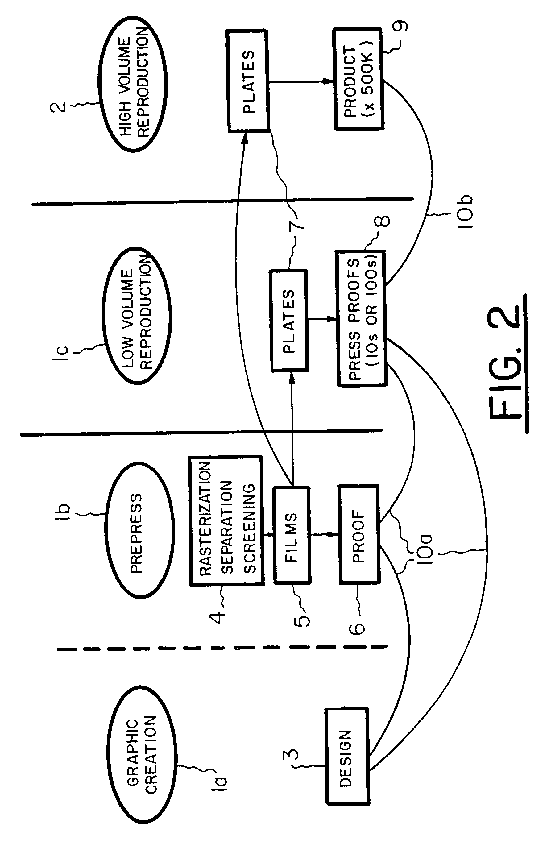
However, acceptance of computer-to-plate technology will blur the boundary between prepress 1b and production 1c.
The transactions in the approval process involve one or more generations of static proofs which are prepared with limited regard for the capabilities of the final, volume-production devices.
The process results in idle time for equipment and personnel and waste of consumables (paper, ink etc.) Furthermore, it usually does not give the print buyer any direct say about the appearance of the ultimate product unless the buyer travels to the printing plant, an expensive proposition.
However, the essential lack of feedback is also prevalent in the commercial environment as well.
Because of the manner in which his subsets are modeled, the method severely limits flexibility in performing GCR.
This has ramifications for the viability of the method for sets of rendering colorants other than those used in the closed printing system, as explained below.
However, calorimetric calibration for the purposes of building gamut descriptions in support of proofing relationships among devices is not disclosed.
In other words, the artificial sensor will be unable to distinguish colors that a human can distinguish.
The problem was that the production equipment changed with time (even within a production cycle) so that static calibration proved inadequate.
Operator override is possible and is necessary when the colorimeter goes out of calibration, since it is not capable of calibration self-check.
The drawback of the Sodergard et al. system is that color control lacks the necessary precision for high quality color reproduction.
This method lacks any provision for calibration or verification of the devices at either end of a link and also lacks the data structures needed to support remote proofing and negotiation of color approval.
Bonino et al. thus employs photometric characterization of devices and lacks a calorimetric characterization.
The MCT thus does not provide a file format defining the full specification of color transformations in the context of distributed production and color-critical remote proofing.
Representation of devices in the ICC Profile Format is limited in supporting “scnr” (scanner).
“mntr” (video display monitor) and “prtr” (printer) device types, and is not readily extendable to other types of devices.
Typically, calibration devices are limited in one or more of the following ways.
First, many of the devices require manual measurements of samples under circumstances conducive to operator error.
An unskilled operator is ill-equipped to recognize likely problems in the data.
Second, an instrument may require physical contact with the copy and consequent scuffing or transfer of fingerprints and skin oils.
Samples are routinely affected by this before they are measured and the accuracy of a dataset is compromised.
The devices clutter the workspace when not in use and require significant operator involvement in measurement.
Third, an instrument may require calibration by the operator.
Likewise, proper use, cleaning and maintenance of white calibration plaques often used in calibration are not usually performed.
Thus, typical calibration instrumentation of a rendering device is not sufficiently fool-proof to serve the intended purpose of automating the process of interdevice color reproduction.

Method used


Image

  • System for distributing and controlling color reproduction at multiple sites
  • System for distributing and controlling color reproduction at multiple sites
  • System for distributing and controlling color reproduction at multiple sites

Examples


Embodiment Construction

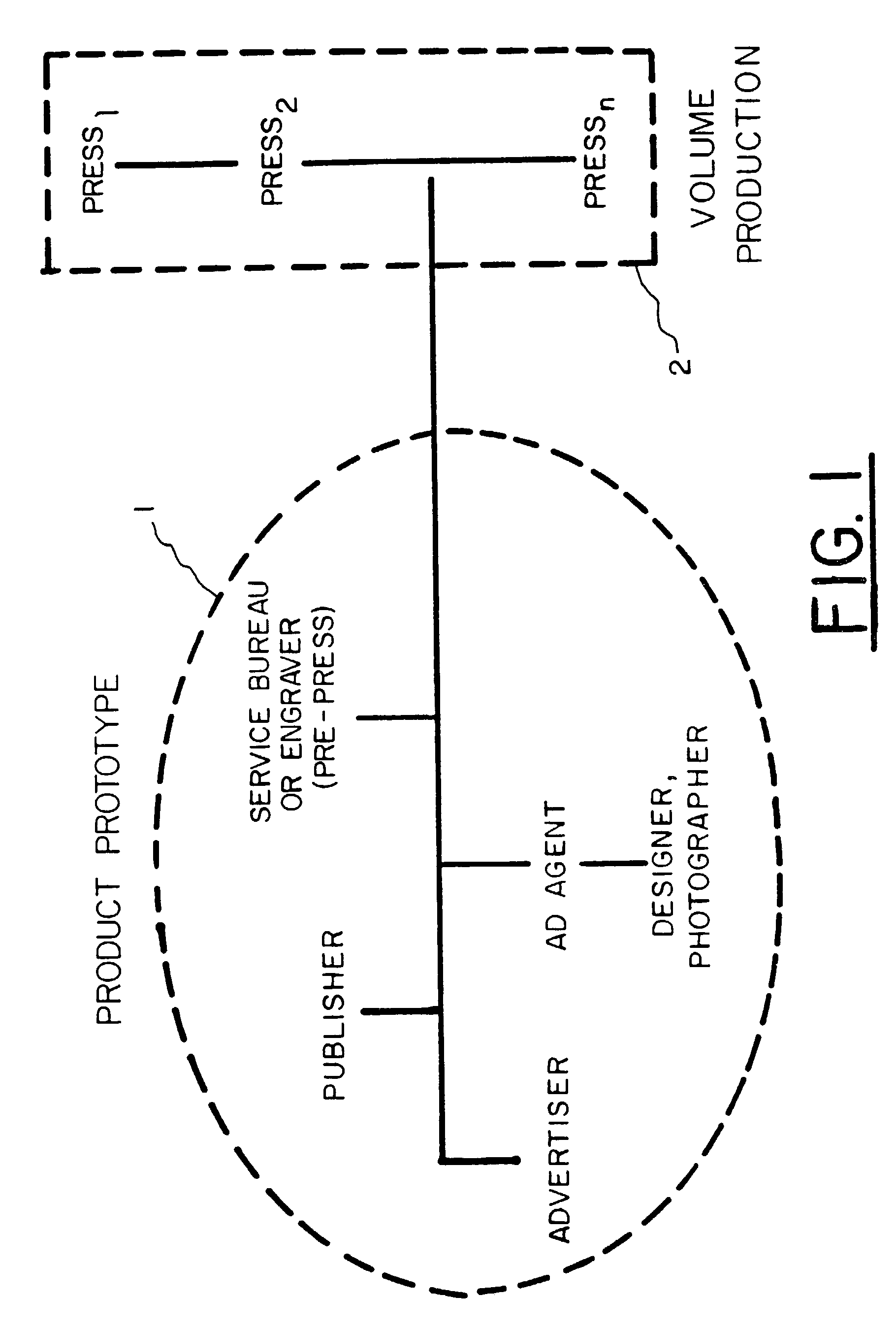
[0117]Referring to FIG. 3A, the system 100 of the present invention is shown. System 100 has a network 11 having a pipe 11a through which multiple nodes (or sites) of network 11 can be linked for data flow between nodes. Network 11 may be a telecommunication network, WAN, LAN (with a server) or Internet based. Two types of nodes are present in system 100, prototype nodes 102 and production nodes 104. For purposes of illustration, only a general node of each type is shown in FIG. 3A, however there may be multiple nodes of each type in network 11. Network 11 is modifiable to be configured by any one node to connect any two or more nodes in system 100. Each node has a micro-processor based computer, with a network communication device, such as a modem, which is part of a system having a rendering device for producing color reproduction and color measuring instrument (CMI) for measuring the color output of the rendering device. The computer may be a programmable general purpose computer...


PUM


Abstract

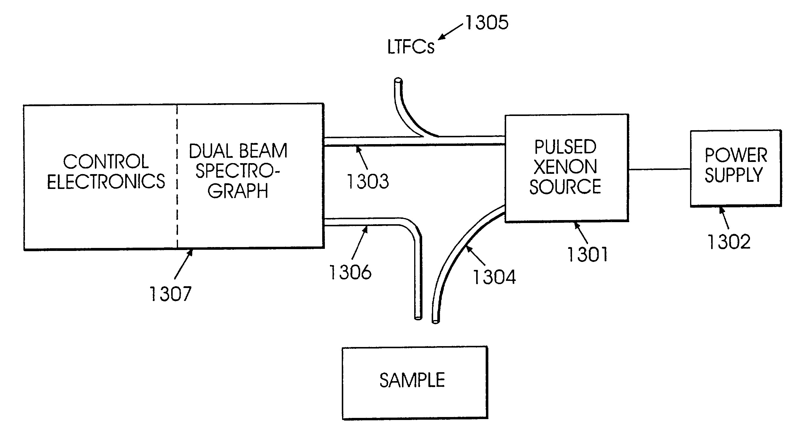
In the color imaging system, multiple rendering devices are provided at different nodes along a network. Each rendering device has a color measurement instrument for calibrating the color presented by the rendering device. A rendering device may represent a color display in which a member surrounds the outer periphery of the screen of the display and a color measuring instrument is coupled to the first member. The color measuring instrument includes a sensor spaced from the screen at an angle with respect to the screen for receiving light from an area of the screen. A rendering device may be a printer in which the measuring of color samples on a sheet rendered by the printer is provided by a sensor coupled to a transport mechanism which moves the sensor and sheet relative to each other, where the sensor provides light from the sample to a spectrograph. The color measuring instruments provide for non-contact measurements of color samples either displayed on a color display, or printed on a sheet, and are self-calibrating by the use of calibration references in the instrument.

Description

[0001]This application is a divisional of U.S. patent application Ser. No. 09 / 139,498, filed Aug. 25, 1998, now U.S. Pat. No. 6,459,425, which claims the benefit of U.S. Provisional Patent Application Ser. No. 60 / 056,947, filed Aug. 25, 1997, and is related to patent application Ser. Ser. No. 08 / 606,883, filed Feb. 26, 1996, now U.S. Pat. No. 6,043,909.FIELD OF THE INVENTION[0002]The present invention relates to a system (method and apparatus) for distributing and controlling color reproduction at multiple sites, and particularly to, a system for distributing and controlling the color output of rendering devices, such as color monitors, proofing devices, and presses, at multiple sites or nodes of a network to provide a uniform appearance of color within the output colors attainable at each rendering device. The invention utilizes a color measurement instrument associated with each rendering device for obtaining color calibration data for calibrating the rendering device. The system ...

Claims


Application Information

Patent Timeline
IPC IPC(8): G01J3/28G01J3/46G09G5/02H04N1/60
CPCG01J3/02G03F7/70058G01J3/0224G01J3/0262G01J3/0291G01J3/28G01J3/46G01J3/462G01J3/463G01J3/465G01J3/524G09G5/02H04N1/6055H04N1/6058G01J3/51G01J3/2823G01J3/0218G01J3/1838G01J2003/2866G09G2320/0276G09G2320/043G09G2320/0606G09G2320/0626G09G2320/066G09G2320/0666G09G2320/0693G09G2320/08G01J2003/283G06T7/90H04N9/69G06T5/77H04N17/02G01B11/002G01J3/505G06T5/40H04N9/643H04N9/646
Inventor HOLUB, RICHARD A.
Owner RAH COLOR TECH
Learn More