
Electronic apparatus and method for manufacturing the same

a technology of electronic equipment and manufacturing method, applied in the field of electronic equipment, can solve the problems of difficult small-size and high-density package electronic equipment, interference of connection jig with components, and insufficient connection spa

Inactive Publication Date: 2007-04-24
DENSO CORP
View PDF13 Cites 27 Cited by
  • Summary
  • Abstract
  • Description
  • Claims
  • Application Information

AI Technical Summary

Benefits of technology

This configuration allows for a small-sized electronic apparatus with a sufficient connection space, preventing interference and enabling efficient wire bonding without obstructing elements, thus achieving miniaturization while maintaining a reliable connection.

Problems solved by technology

However, if the connection space for the connection between the wiring board and the connector units is narrowed, a connection device and a connection jig will interfere with components adjacent thereto when performing the connection operation.
Therefore, it is difficult to small-size and high-density package the electronic apparatus.
However, in this case, a bonder 300 of a wire bonding device interferes with a sidewall of the case unit 10, so that the wire bonding becomes difficult.
As a result, the electronic apparatus becomes large.
Therefore, it is difficult to small-size the electronic apparatus in this case.
That is, an interference between the bonder 300 of the wire bonding device and the connector unit 30 is caused, so that the wire bonding becomes difficult.
Thus, the size of the electronic apparatus becomes large, so that the miniaturization thereof becomes difficult.
The above-described problem is not only caused in the case where the connection between the wiring board and the connector unit is established via the wire bonding, but also caused in the case where a flexible printed circuit board is used as the connection member.
In this case, a pressing / heating jig for the connection interferes with the above-described interfering elements.
Therefore, according to the conventional electronic apparatus (referring to first and second comparison examples), there exits a trade-off relationship between realization of a sufficient connection space and realization of a miniaturization of the electronic apparatus, so that it is difficult to satisfy these requirements simultaneously.

Method used


Image

  • Electronic apparatus and method for manufacturing the same
  • Electronic apparatus and method for manufacturing the same
  • Electronic apparatus and method for manufacturing the same

Examples


##able embodiment

(Preferable Embodiment)

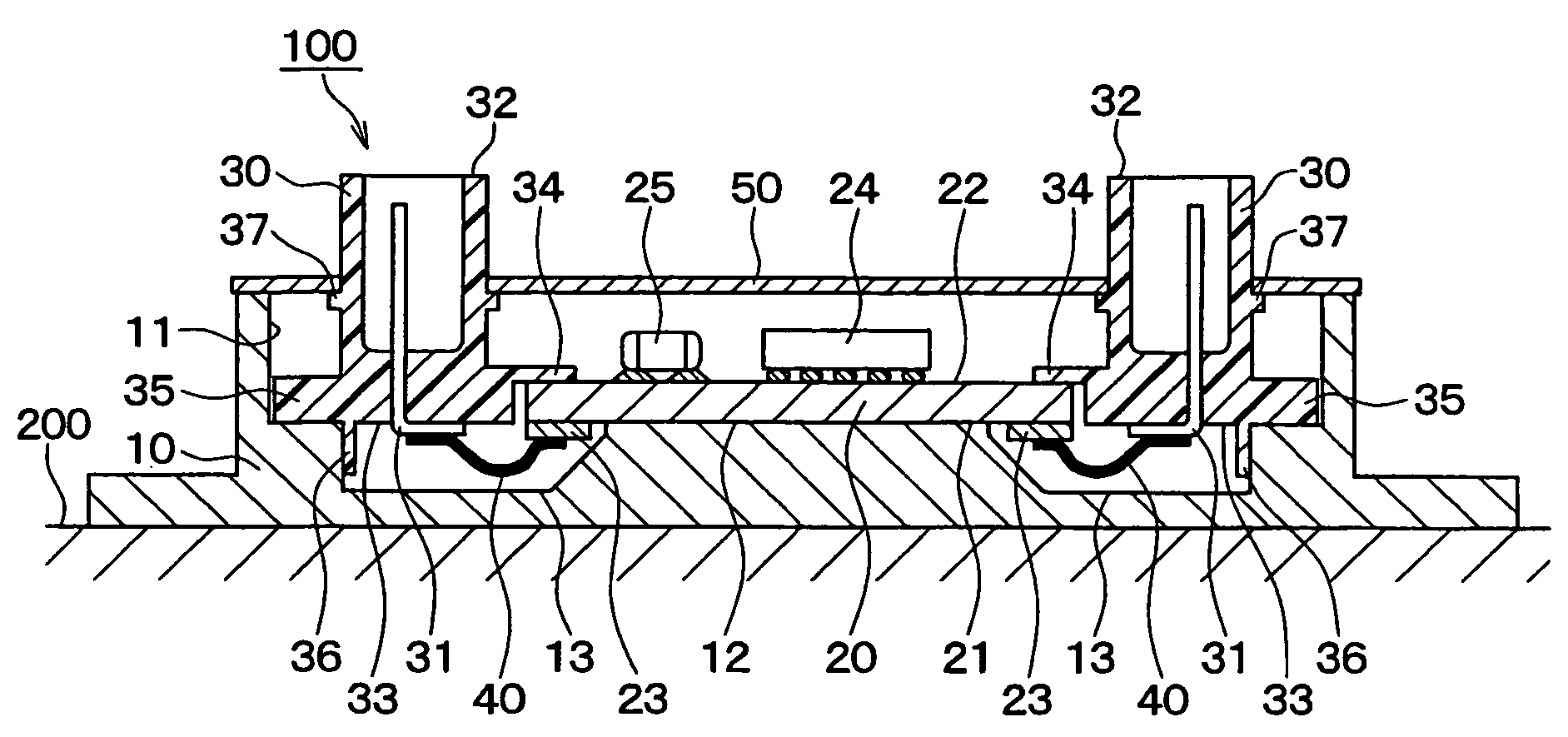
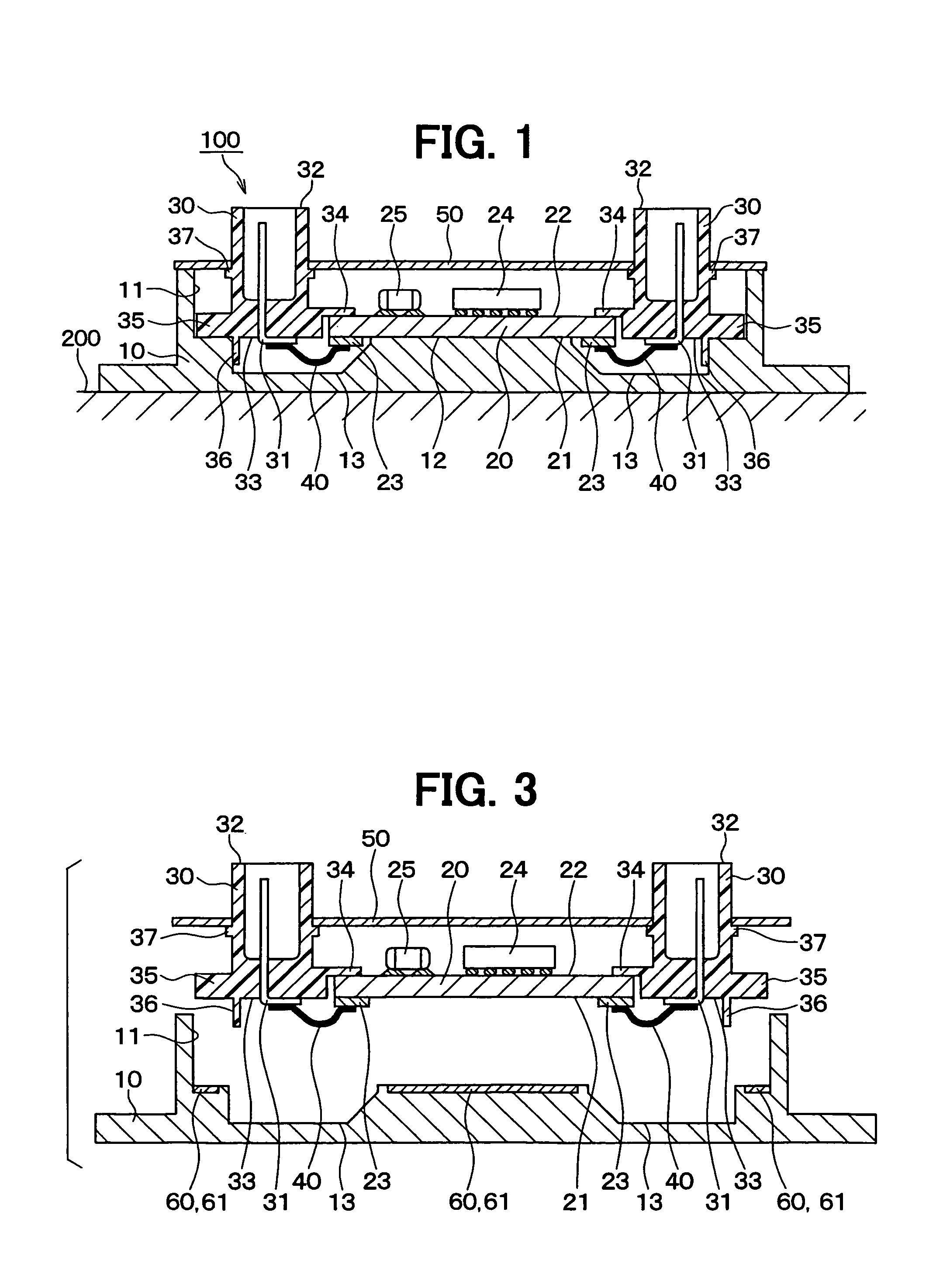
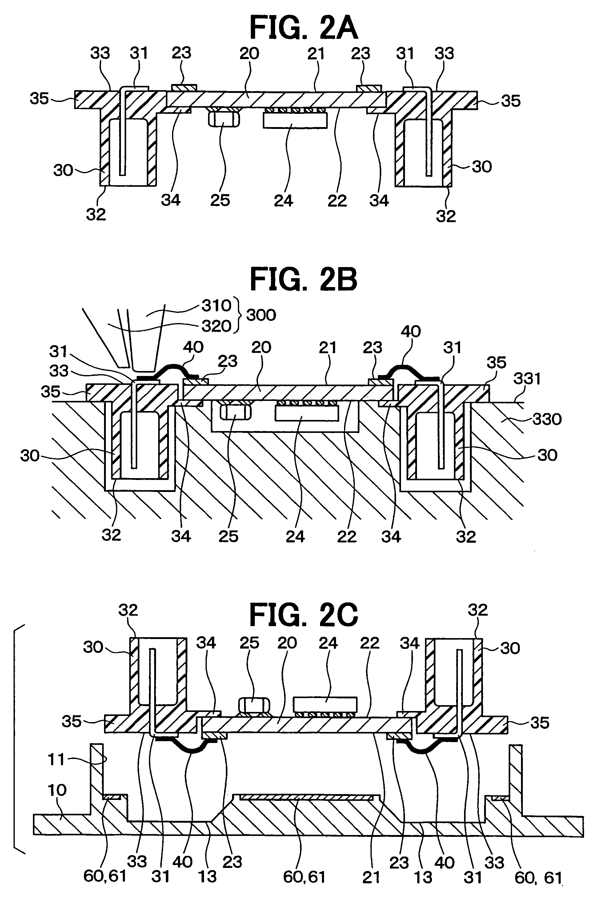
[0041]An electronic apparatus 100 according to a preferable embodiment of the present invention will be described with reference to FIGS. 1–3. The electronic apparatus 100 can be suitably used for an engine ECU or the like. In this case, referring to FIG. 1, the electronic apparatus 100 can be attached to an attachment member 200 of an engine room of a vehicle, for example.

[0042]As shown in FIG. 1, the electronic apparatus 100 is mainly constructed with a wiring board 20, at least one connector unit 30 (e.g., two connector units 30 as shown in FIG. 1) through which the electronic apparatus 100 is connected with the external, at least one connection member 40 (e.g., two connection members 40 as shown in FIG. 1) for electrically connecting the wiring board 20 with the connector unit 30, and a case unit 10 at which the wiring board 20 and the connector unit 30 are mounted. In this embodiment, the connection member 40 is constructed of a bonding wire made of gold,...


PUM


Abstract

An electronic apparatus has a wiring board and connector units which are mounted at a case unit. The connector unit has an external connection surface connected with the external and a terminal installation surface, which is substantially flat and positioned at an opposite side to the external connection surface. A terminal of the connector unit is electrically connected with a pad positioned at a first surface of the wiring board via a connection member. The wiring board and the connector unit which are integrated are mounted at the case unit, with the first surface and the terminal installation surface facing the case unit. The case unit has an installation surface at which a recess for accommodating therein the connection member is arranged.

Description

CROSS REFERENCE TO RELATED APPLICATION[0001]This application is based on a Japanese Patent Application No. 2005-115625 filed on Apr. 13, 2005, the disclosure of which is incorporated herein by reference.FIELD OF THE INVENTION[0002]The present invention relates to an electronic apparatus and a method for manufacturing the same, in which a wiring board and a connector unit for an external connection are electrically connected with each other via a connection member and mounted at a case unit.BACKGROUND OF THE INVENTION[0003]Generally, an electronic apparatus is provided with a wiring board, connector units (for external connection) arranged at the periphery of the wiring board, connection members for electrically connecting the wiring board with the connector units, and a case unit at which the wiring board and the connector units are mounted.[0004]Recently, it is preferable for the wiring board to be miniaturized, that is, a connection space for the connection between the wiring boar...

Claims


Application Information

Patent Timeline
Patent Type & Authority Patents(United States)
IPC IPC(8): H05K1/11H05K1/14
CPCH05K3/3405H05K5/0069H05K3/0061H05K3/3415H05K3/3421H05K2201/09745H05K2201/10189H05K2201/10446H05K2203/0173H01L2224/16225H01L2924/19105H01L2924/19107H01L2924/00014H01L2924/00011H01L2224/0401
Inventor NAKANO, TETSUOMAEDA, YUKIHIRO
Owner DENSO CORP
Learn More