Mirror system and control method therefor

a mirror system and mirror technology, applied in the field of mirror systems, can solve the problems of difficult to present an appropriate video to the treatment acceptor, the treatment acceptor is difficult to simultaneously observe the reflection image and the presentation image,

Active Publication Date: 2013-10-31
CANON KK
View PDF3 Cites 78 Cited by
  • Summary
  • Abstract
  • Description
  • Claims
  • Application Information

AI Technical Summary

Benefits of technology

[0012]In one aspect, a mirror system for displaying an image on a mirror surface, comprising: a mirror which reflects incident light from an object facing on a front surface side to present a reflected image, and transmits incident light from a rear surface; a display unit configured to generate a presentation image to be superimposed on the reflected image; an

Problems solved by technology

If, therefore, the above-described system applications present the posture of the treatment acceptor and its evaluation index, the following problems arise.
That is, since the focal length and the angle of convergence of the reflected image of the treatment acceptor are different from those of an image (to be referred to as a “presentation image” hereinafter) presented as an evaluation index video, it is difficult for the treatment acceptor to simultaneously observe his/her reflected image and the presentation image without changing the fixation point.
In this case, however,

Method used


Image

  • Mirror system and control method therefor
  • Mirror system and control method therefor
  • Mirror system and control method therefor

Examples


first embodiment

Modification of First Embodiment

[0045]In FIG. 3, the virtual image 321 need not always be at the same depth as that of the reflected image of the treatment acceptor 300. The virtual image 321 need only be presented as an image with a depth according to the distance between the treatment acceptor 300 and the half mirror 110.

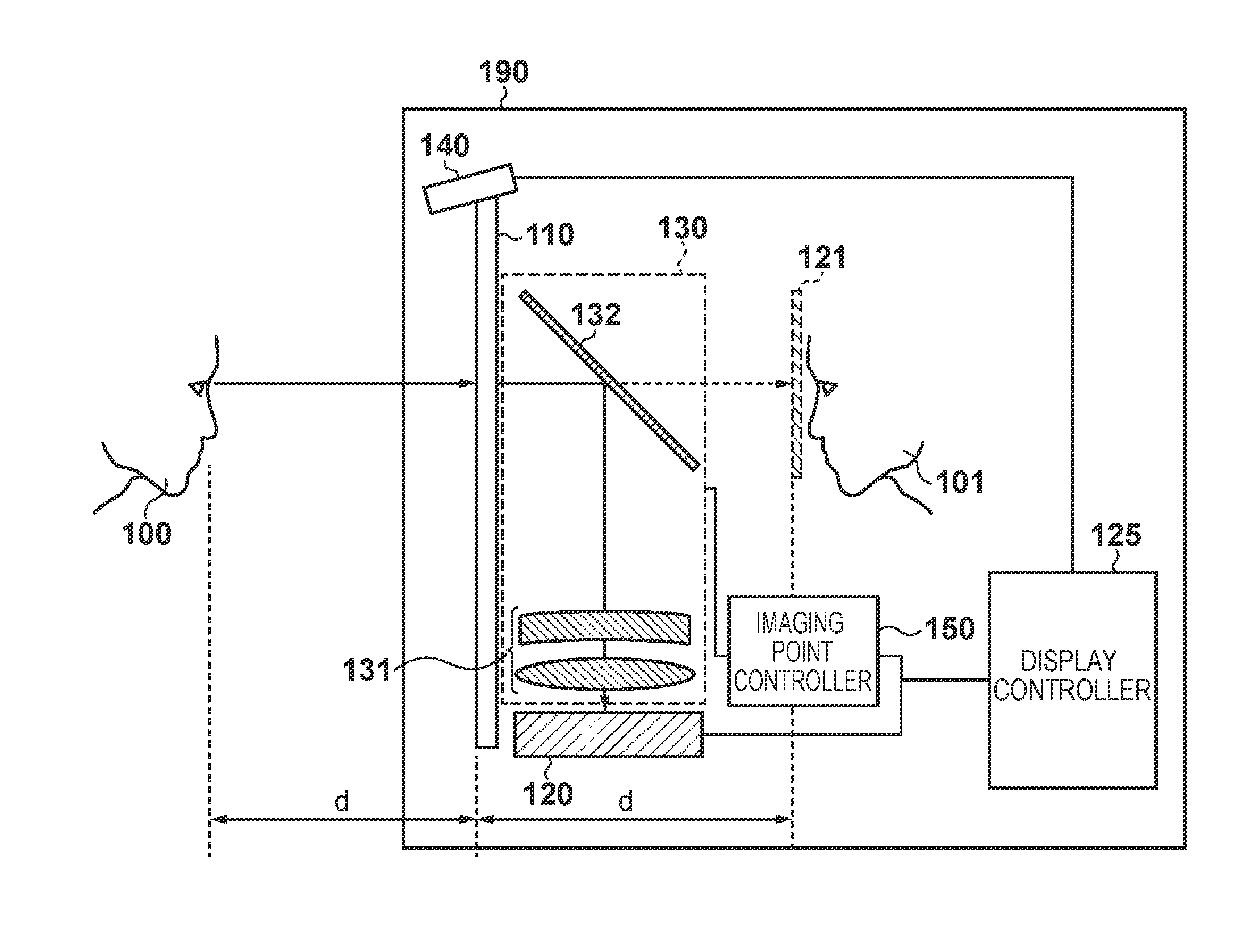
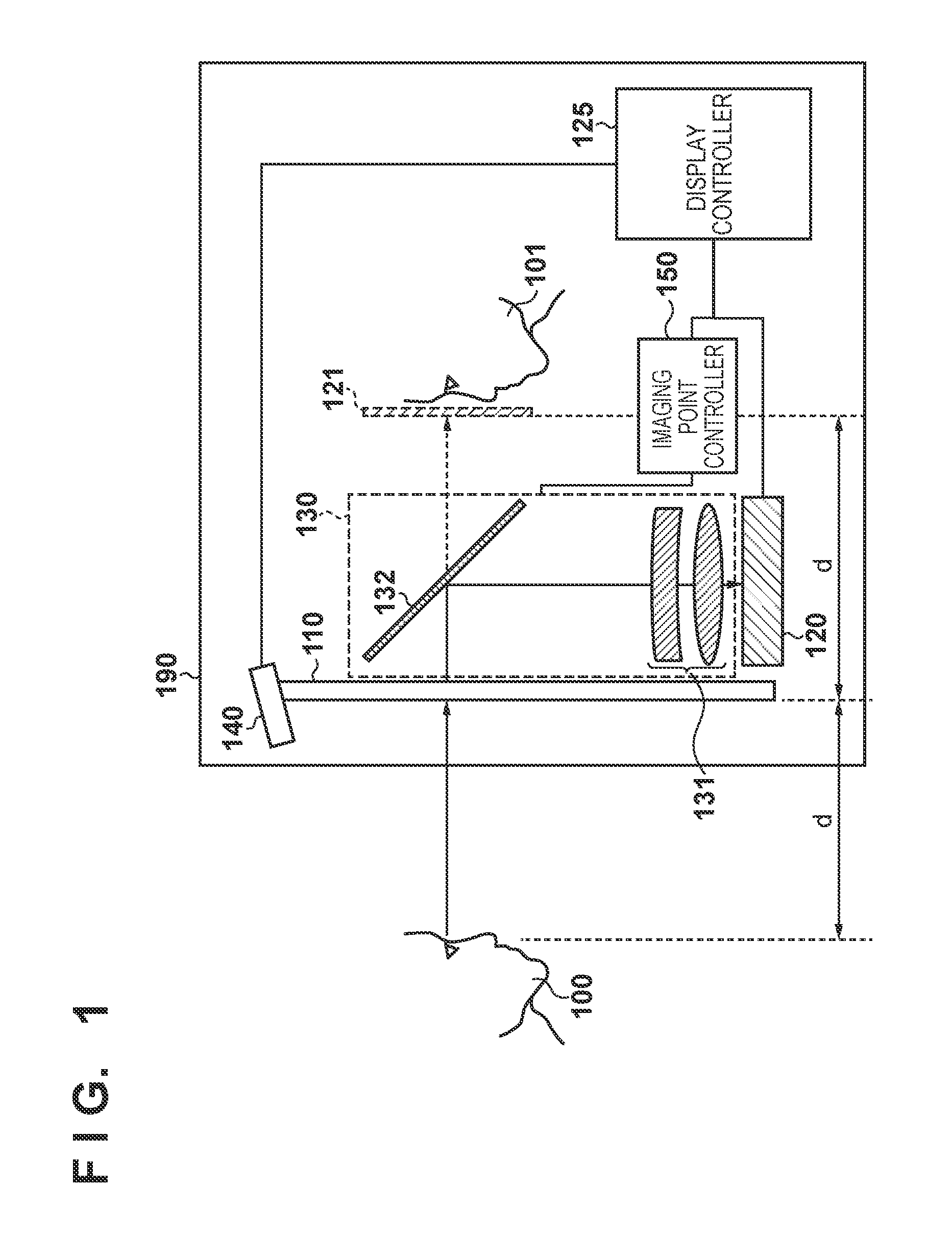
[0046]In the above embodiment, the presentation image displayed on the image display unit 120 is guided to the rear surface of the mirror using the half mirror 110 to present the presentation image to the user of the system. The present invention is not limited to the half mirror and, for example, a total reflection mirror may be used as long as it can present the reflected image and presentation image on planes with the same depth.

[0047]Furthermore, in the above embodiment, the object position acquisition unit 140 is a stereo camera. The present invention is not limited to such an image capturing apparatus, and it is only necessary to measure the depth position (...

second embodiment

[0052]The second embodiment of the present invention will be described below. The second embodiment shows a case in which in the mirror system shown in the above-described first embodiment, a plurality of persons exist as objects, and a so-called simultaneous interpretation system which interprets the languages of the persons is implemented. Note that in the mirror system according to the second embodiment, the same components as those shown in FIG. 1 in the above-described first embodiment have the same reference numerals, and a description thereof will be omitted.

[0053][System Overview]

[0054]FIG. 4 shows a state 450 in which a half mirror 110 shows the reflected images of a plurality of persons according to the second embodiment. In the state 450 shown in FIG. 4, two persons exist in front of the half mirror 110, which shows reflected images 400 and 401 of the respective persons. More specifically, the first person of the reflected image 400 is standing at a distance d1 from the h...

third embodiment

[0070]The third embodiment of the present invention will be described below. The third embodiment shows a case in which in the mirror system shown in the above-described first embodiment, a system used by the user to check the form of a game or sport in front of a mirror is implemented. That is, the system individually presents virtual images with different depths for partial regions (parts) of the body of the user. Note that in the mirror system according to the third embodiment, the same components as those shown in FIG. 1 in the above-described first embodiment have the same reference numerals, and a description thereof will be omitted.

[0071]FIG. 7 is a view showing the use of the mirror system according to the third embodiment, in which a half mirror 110 shows a reflected image 720 of a user 710 as an object which is standing and taking a predetermined pose for a sport or game in front of the half mirror 110. In this example, a head 711, a left hand 712, a right hand 713, and a ...


PUM


Abstract

In a mirror system for displaying an image on a mirror surface, a mirror reflects incident light from an object facing its front surface side to present a reflected image, and transmits incident light from its rear surface. A display unit generates a presentation image to be superimposed on the reflected image. An optical unit is arranged between the display unit and the rear surface of the mirror, and images the presentation image. An acquisition unit acquires distance information between the object and the mirror. A controller controls the imaging point of the presentation image by the optical unit according to the distance information.

Description

BACKGROUND OF THE INVENTION[0001]1. Field of the Invention[0002]The present invention relates to a mirror system for superimposing and displaying an arbitrary image on the reflected image of an object.[0003]2. Description of the Related Art[0004]There have been proposed various mirror systems for displaying not only a reflected image but also a video on a mirror surface.[0005]As applications of such a mirror system, a rehabilitation system for recovering the functions of a human body and a system for determining the quality of physical exercises for maintaining health have been proposed. In these system applications, it is expected to achieve effective rehabilitation and training by presenting, on a mirror surface, a video (to be referred to as an “evaluation index video” hereinafter) serving as an evaluation index such as the posture evaluation result and a past state of a treatment acceptor, and model movement by a trainer simultaneously with the reflected image of the treatment a...

Claims


Application Information

Patent Timeline
IPC IPC(8): G02B27/01H04N5/232G06T11/60
CPCG02B27/0101G06T11/60H04N5/23293G06T11/00H04N23/61H04N23/635
Inventor KATANO, YASUOMATSUGU, MASAKAZUSUZUKI, MASAHIRO
Owner CANON KK
Why Eureka
Try Eureka