Transmitting device, receiving device, and method for transmitting operational information in receiving device

a technology of receiving device and transmitting device, which is applied in the direction of two-way working system, television system, instruments, etc., can solve problems such as difficulty in easy operation

Inactive Publication Date: 2009-06-04
SONY CORP
View PDF26 Cites 126 Cited by
  • Summary
  • Abstract
  • Description
  • Claims
  • Application Information

AI Technical Summary

Problems solved by technology

In either case, it is difficult to operate easily unlike a case of a television channel operation, etc., while viewing a large screen of the television.
Such a problem occurs also in a case of an AV system in which a personal computer is connected to the television receiver by an HDMI cable, for example, and displays an image based on a video signal transmitted from the personal computer to a display panel of the television receiver, and a user operates the personal computer.

Method used


Image

  • Transmitting device, receiving device, and method for transmitting operational information in receiving device
  • Transmitting device, receiving device, and method for transmitting operational information in receiving device
  • Transmitting device, receiving device, and method for transmitting operational information in receiving device

Examples


Embodiment Construction

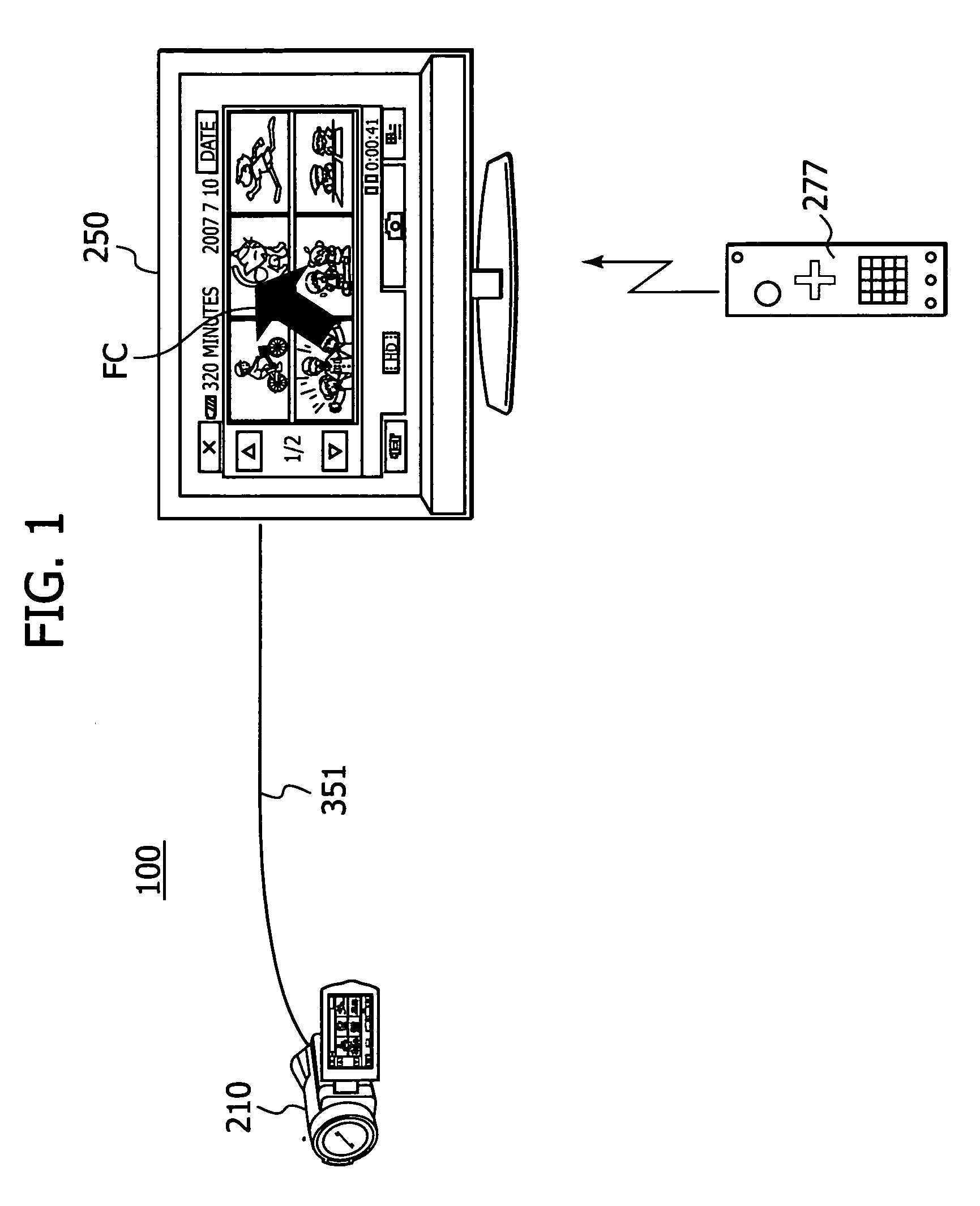
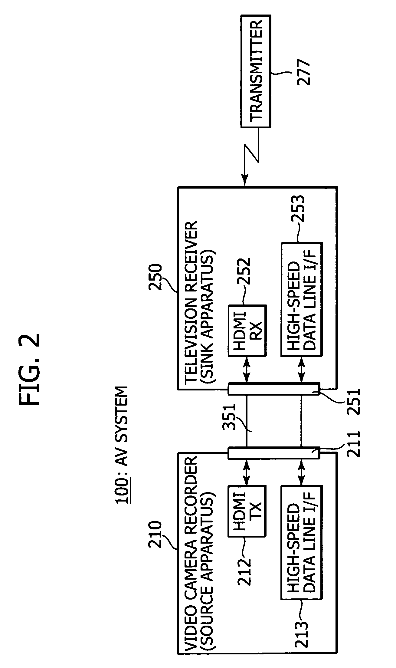
[0063]Hereinafter, with reference to drawings, an embodiment of the present invention will be described. FIG. 1 and FIG. 2 each show a configuration example of an AV (Audio Visual) system 100 as an embodiment.

[0064]The AV system 100 is configured so that that a video camera recorder 210 as a source apparatus and a television receiver 250 as a sink apparatus are connected via an HDMI cable 351. A remote control transmitter 277 of the television receiver 250 is compatible with a free cursor.

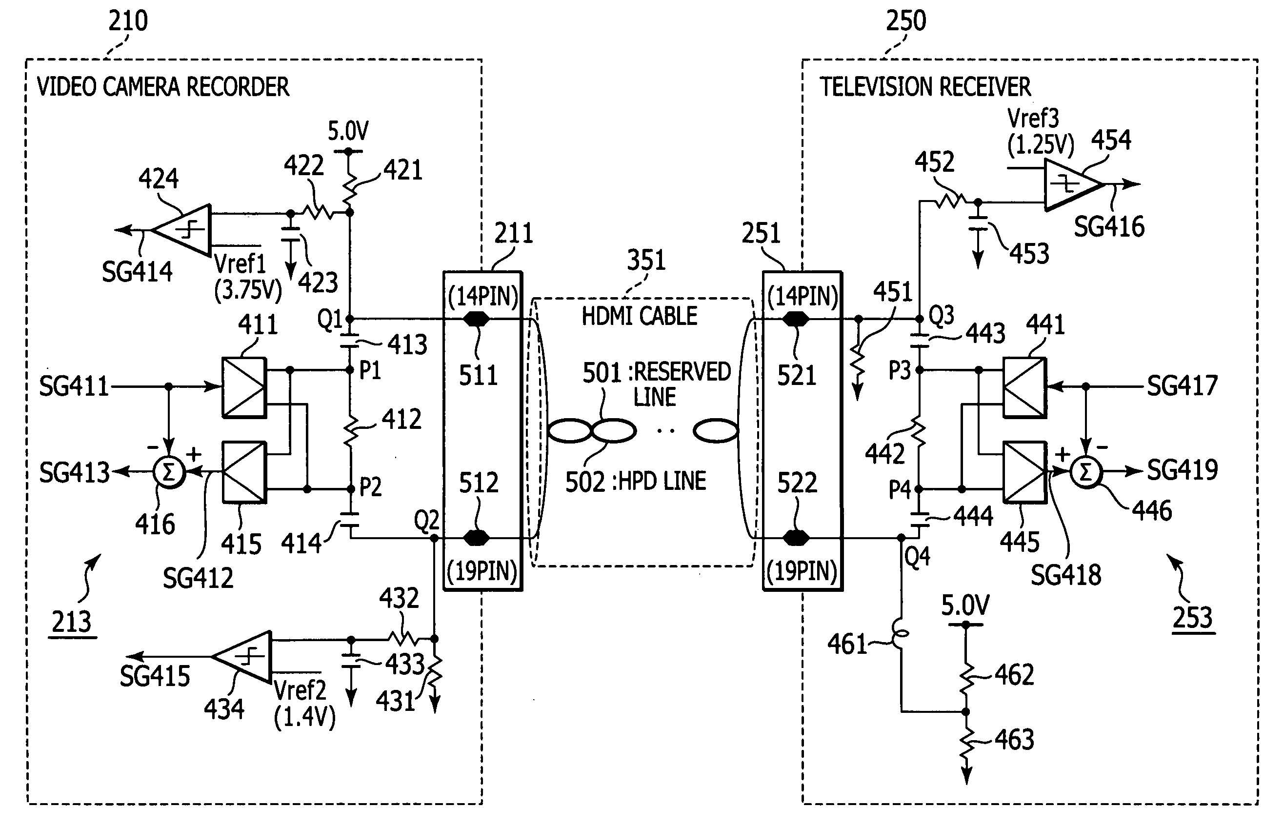
[0065]As shown in FIG. 2, the video camera recorder 210 and the television receiver 250 are connected via the HDMI cable 351. The video camera recorder 210 is provided with an HDMI terminal 211. The HDMI terminal 211 is connected with an HDMI transmitting unit (HDMITX) 212 and a high-speed data line interface (I / F) 213. The television receiver 250 is provided with an HDMI terminal 251. The HDMI terminal 251 is connected with an HDMI receiving unit (HDMIRX) 252 and a high-speed data line interface (...


PUM


Abstract

A transmitting device includes a video-signal output unit, an image displaying unit, an information receiving unit, and a controller. The video-signal output unit outputs a video signal. The image displaying unit displays an image based on the video signal outputted from the video-signal output unit, on a first image display element. The signal transmitting unit transmits the video signal outputted from the video-signal output unit, to an external apparatus via a transmission path. The information receiving unit receives operational information transmitted from the external apparatus, on a display screen of a second image display of the external apparatus. The controller controls at least an operation of the video-signal output unit on the basis of the operational information received by the information receiving unit.

Description

CROSS-REFERENCE TO RELATED APPLICATIONS[0001]The present application claims benefit of priority of Japanese patent Application No. 2007-309741 filed in the Japanese Patent Office on Nov. 30, 2007, the entire disclosure of which is incorporated herein by reference.BACKGROUND OF THE INVENTION[0002]1. Field of the Invention[0003]The present invention relates to a transmitting device, a receiving device, and a method for transmitting operational information in the receiving device.[0004]2. Description of Related Art[0005]In recent years, an HDMI (High Definition Multimedia Interface) has been widely used as a communication interface for transmitting a digital video signal, i.e., a non-compressed (baseband) video signal (hereinafter referred to as “image data”) and a digital audio signal (hereinafter referred to as “audio data”) accompanying the video signal, at high-speed, from a DVD (Digital Versatile Disc) recorder, a set top box, and other AV (Audio Visual) sources, for example, to a...

Claims


Application Information

Patent Timeline
Patent Type & Authority Applications(United States)
IPC IPC(8): H04N5/04H04N5/44H04N7/173
CPCG09G5/006G09G2370/04G09G2370/045G09G2370/047G09G2370/12H04N21/4122H04N21/42204H04N21/4316H04N21/43622H04N21/43635H04N21/485
Inventor KONDO, KAZUMOTONINOMIYA, NAOKONAKAJIMA, YASUHISA
Owner SONY CORP
Why Eureka
Try Eureka