Head driving mechanism and printing apparatus

Active Publication Date: 2013-10-31
SEIKO EPSON CORP
View PDF3 Cites 2 Cited by
  • Summary
  • Abstract
  • Description
  • Claims
  • Application Information

AI Technical Summary

Benefits of technology

The present invention provides a small-sized head driving mechanism that can be made at a lower cost. This mechanism allows for movement of printing heads in different directions. Additionally, a printing apparatus that includes this head driving mechanism is also provided. The technical effect of this invention is to improve the efficiency and flexibility of printing.

Problems solved by technology

However, no specific reference is made in JP-A-2011-67964 about such a positioning method.
However, providing the same number of head driving mechanisms as that of the printing heads not only constitutes a major factor that increases the size and cost of the printing apparatus, but also makes it difficult to locate the printing heads at the correct position with high accuracy, because of individual variation among the head driving mechanisms.
Further, in the case of driving the printing head by using the cam, providing the head driving mechanisms for the respective printing heads incurs a positioning error among the printing heads, originating from individual variation among the cams of the head driving mechanisms, which leads to degradation in printing accuracy.

Method used


Image

  • Head driving mechanism and printing apparatus
  • Head driving mechanism and printing apparatus
  • Head driving mechanism and printing apparatus

Examples


Embodiment Construction

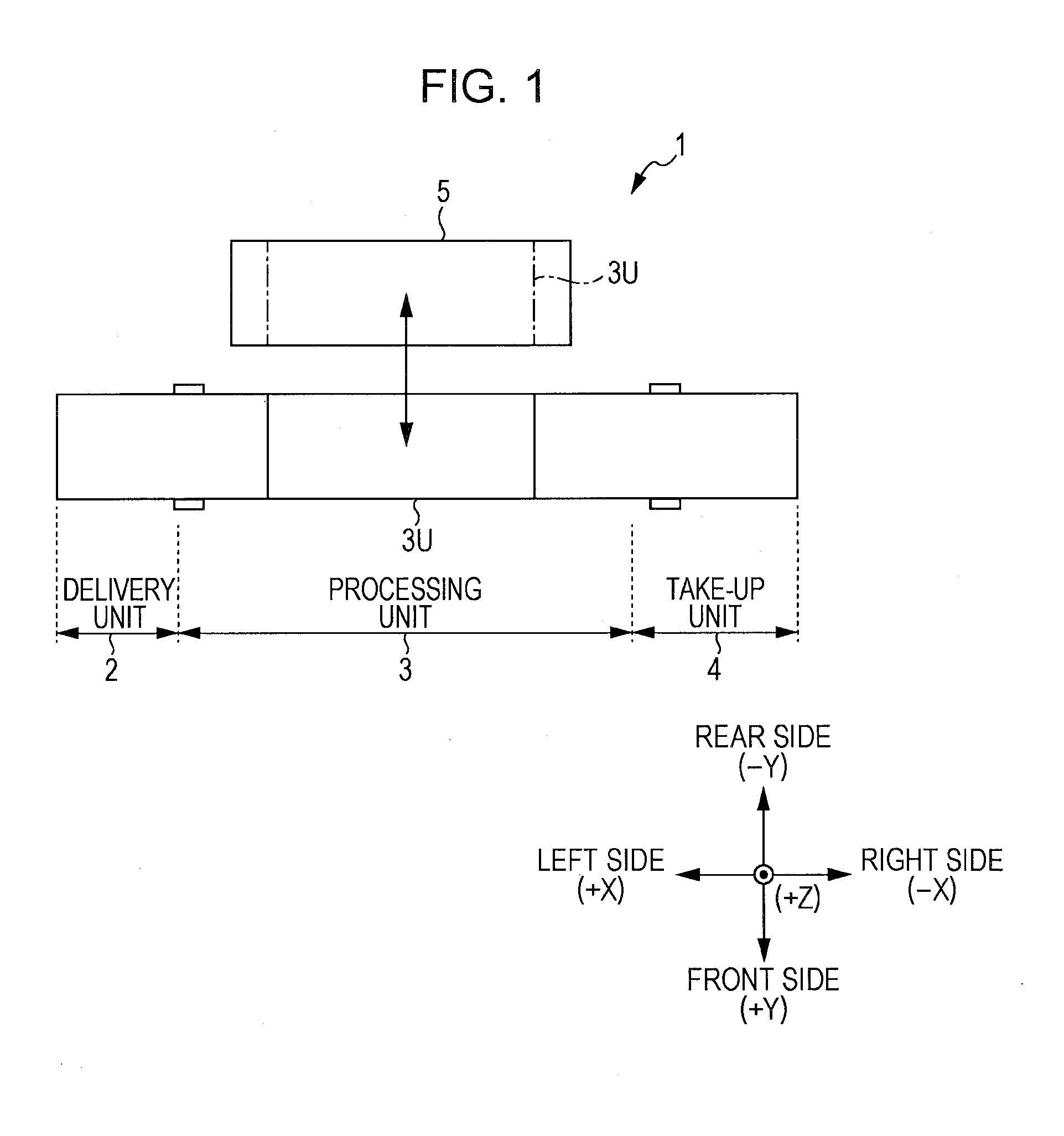
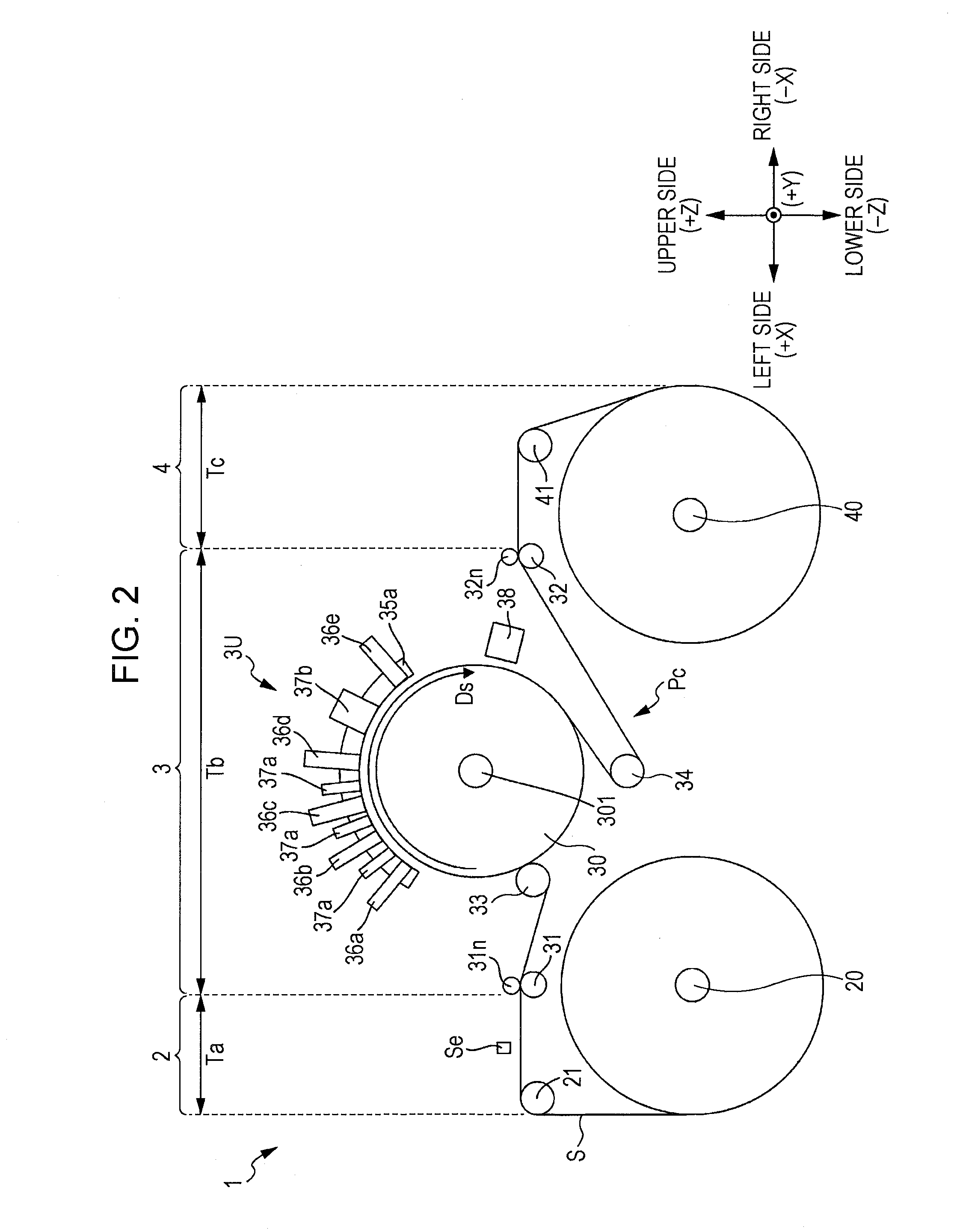
[0025]FIG. 1 is a schematic plan view showing a layout of a printing apparatus including a head driving mechanism according to an embodiment of the present invention. FIG. 2 is a schematic front view of the printing apparatus shown in FIG. 1. The printing apparatus 1 includes a delivery unit 2, processing unit 3, and a take-up unit 4 aligned in a left-right direction on the front side of the apparatus, and a maintenance unit 5 located on the rear side of the processing unit 3, which includes a processor 3U set to move interlocked with the processing unit 3, with respect to the maintenance unit 5. In these drawings, as well as in the drawings to be referred to later, a three-dimensional coordinate system is adapted, in which the axes respectively correspond to the left-right direction X, a front-back direction Y, and a vertical direction Z of the printing apparatus 1.

[0026]As shown in FIG. 2, in the printing apparatus 1 the delivery unit 2 and the take-up unit 4 include a delivery sh...


PUM


Abstract

A head driving mechanism includes a first cam follower an end portion of which is attached to a first holding unit and the other end portion of which includes a first sliding-contact surface disposed in sliding contact with a cam, and a second cam follower an end portion of which is attached to the second holding unit and the other end portion of which includes a second sliding-contact surface disposed in sliding contact with the cam. The first cam follower and the second cam follower are each displaced by rotation of the cam so as to move the first printing head and the second printing head, while the first sliding-contact surface and the second sliding-contact surface are in sliding contact with an outer circumferential surface of the cam.

Description

CROSS-REFERENCE TO RELATED APPLICATIONS[0001]The entire disclosure of Japanese Patent Application No.2012-100983, filed Apr. 26, 2012 is expressly incorporated by reference herein.BACKGROUND[0002]1. Technical Field[0003]The present invention relates to a head driving mechanism that drives a plurality of printing heads, and a printing apparatus including the head driving mechanism.[0004]2. Related Art[0005]JP-A-2011-67964 (in particular, see FIG. 1) discloses a printing apparatus that dispenses a liquid such as ink or recording fluid from a plurality of printing heads onto a recording medium such as a film, to thereby record color images. In this apparatus, the recording medium is wound, with a predetermined tension applied thereto, around a circular column-shaped platen drum the recording medium, and supported on the curved surface of the platen drum. The plurality of printing heads are provided around the circumferential surface of the platen drum.[0006]To record high-quality image...

Claims


Application Information

Patent Timeline
IPC IPC(8): B41J23/12
CPCB41J23/12B41J25/34B41J2025/008
Inventor SHIIYA, TOMOYUKI
Owner SEIKO EPSON CORP
Why Eureka
Try Eureka