Electric motor system

a technology of electric motors and motor components, applied in the direction of dynamo-electric converter control, dynamo-electric gear control, magnetic circuit shape/form/construction, etc., can solve the problems of high power switching elements, difficult balancing of electric current between igbts, and increasing the cost of manufacturing inverters, so as to reduce the size and manufacturing costs of electric motor systems. , the effect of high efficiency

Active Publication Date: 2016-01-05
MOOG JAPAN
View PDF6 Cites 6 Cited by
  • Summary
  • Abstract
  • Description
  • Claims
  • Application Information

AI Technical Summary

Benefits of technology

[0019]Thus several advantages of one or more aspects are to provide a high power, high efficiency electric motor system without increasing the power of the switching elements, such as IGBTs, used in the inverter, and to reduce the size and the manufacturing costs of the electric motor system. These and other advantages of one or more aspects will become apparent from a consideration of the ensuing description and accompanying drawings.

Problems solved by technology

However, because the IGBTs are connected in parallel, balancing the electric current between the IGBTs is difficult, and typically it is necessary to have circuit designs that take into account a derating of between 10 and 30% (as it is necessary to use a device that has a rating that has a margin relative to the power use).
Because of this, it is necessary to use IGBTs that have large rated powers relative to the maximum electric current values required by the electric motor, increasing the cost of manufacturing the inverters.
This motor provides a high power inverter motor without requiring high power switching elements, which are relatively expensive when compared to low power ones.
However, the motors disclosed in the references described above are induction motors, and thus have fundamentally different structures from synchronous motors that use permanent magnets in the rotors.

Method used


Image

  • Electric motor system
  • Electric motor system
  • Electric motor system

Examples


first embodiment

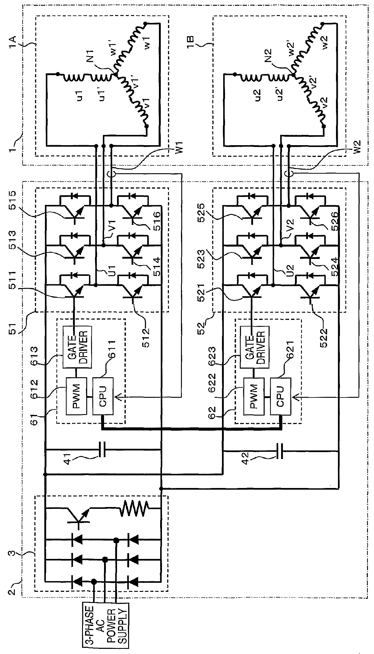
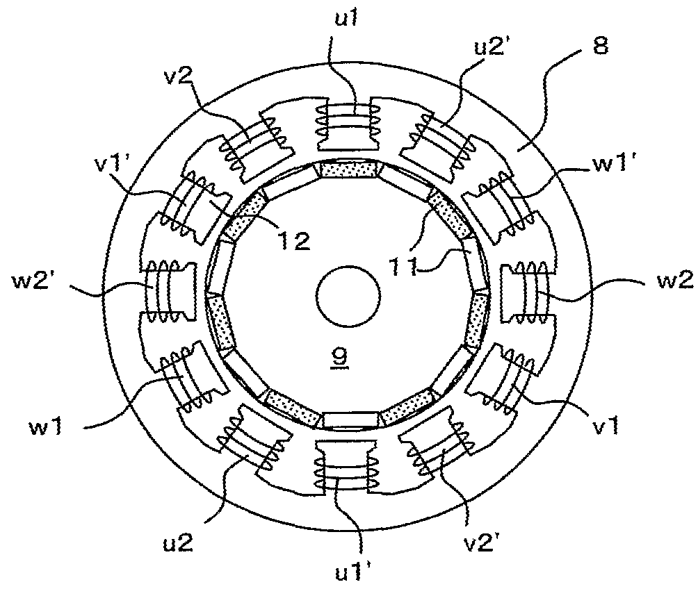
[0029]FIG. 1 illustrates the electric motor system. As shown, the electric motor system broadly comprises electric motor 1 and driving circuit 2. Electric motor 1 has stator 8 and rotor 9. Two three phase coil sets, 1A and 1B, are wound around poles 12 of stator 8. Rotor 9 has permanent magnets 11. Driving circuit 2 produces two three-phase driving voltages for driving electric motor 1.

[0030]Driving circuit 2 contains converter unit 3 (for converting three-phase alternating current power source 5 into direct current), rectifying capacitors 41 and 42, control units 61 and 62 (for generating respective three-phase PWM signals), and first and second inverter units 51 and 52 (for converting the direct current into the desired alternating current through switching operations as controlled by control units 61 and 62).

[0031]Control unit 61 provides inverter unit 51 the proper switch signals to generate three-phase driving voltages U1, W1, and V1 at the proper frequency and phase. Control u...

second embodiment

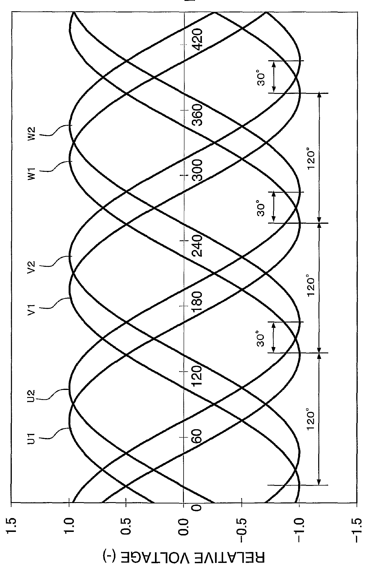
[0055]FIG. 6 illustrates the phases of the three-phase driving voltages in the In this figure, the horizontal axis shows the phases of the driving voltages and the vertical axis shows the driving voltages (the relative voltages). Driving voltages U3, V3, and W3 of third inverter unit 53 have phase differences of 0°, 120°, and 240°, respectively, when driving voltage U1 is used as the reference. Furthermore, driving voltages U4, V4, and W4 of fourth inverter unit 54 have phase differences of 30°, 150°, and 270°, respectively, when driving voltage U1 is used as the reference. Consequently, as shown in FIG. 6, driving voltages U1, V1, and W1, output from first inverter unit 51, and driving voltages U3, V3, and W3, output from third inverter unit 53, have substantially identical phases. Similarly, driving voltages U2, V2, and W2, output from second inverter unit 52, and driving voltages U4, V4, and W4, output from fourth inverter unit 54, have substantially identical phases. Driving vo...


PUM


Abstract

An electric motor system including: a rotor (9); a stator (8); the rotor and the stator being mounted for movement relative to one another; the rotor having multiple magnetic poles (11); the stator having multiple salient poles (12) facing the magnetic poles; a first coil set (1A) and a second coil set (1B); the first coil set having three phases, each of the phases comprising a first coil (u1, v1, w1) and a second coil (u1 v1′, w1′) connected in series and wrapped around different of the salient poles in different directions relative to the rotor; the second coil set having three phases, each of the phases comprising a first coil (u2, v2, w2) and a second coil (u2′, v2′, w2′) connected in series and wrapped around different of the salient poles in different directions relative to the rotor; a driver (2) configured to drive the first coil set with a first three-phase voltage (U1, V1, W1) and to drive the second coil set with a second three-phase voltage (U2, V2, W2); the driver configured to drive the first phase of the first three-phase voltage and the first phase of the second three-phase voltage with a relative phase shift.

Description

TECHNICAL FIELD[0001]The present invention relates generally to electric motor systems and, more particularly, to electric motor systems having a rotor with at least one permanent magnet, a stator with salient poles, a plurality of multi-phase coil sets with coils wound on salient poles of the stator, and a driver for supplying a plurality of multi-phase electric currents.BACKGROUND ART[0002]Recently, the appearance of powerful rare-earth magnets on the market has enabled the development of small, high efficiency, high power permanent magnet-type synchronous motors that use rare-earth magnets in the rotors. These motors are used as motive sources and control driver sources in a variety of industries. In order to use such motors at high power, there have been increases in the electric current capacities of inverters for motors.[0003]One example of a conventional electric motor system is illustrated in FIG. 7. This electric motor system has two three-phase coil sets with distributed w...

Claims


Application Information

Patent Timeline
Patent Type & Authority Patents(United States)
IPC IPC(8): H02P23/00H02P25/02H02P25/22H02K1/14H02K3/18H02K21/14H02M7/493H02P21/22H02P27/06H02P27/08
CPCH02P25/021H02P25/22H02P25/024H02K3/18H02K3/34H02P27/00
Inventor BABA, TSUTOMUFUJIWARA, KENJI
Owner MOOG JAPAN
Why Eureka
Try Eureka